Multi-redundancy landing gear electric retraction controller

A landing gear and controller technology, applied in general control systems, control/adjustment systems, instruments, etc., can solve the problems of increasing aircraft weight, aircraft bomb weight, low utilization rate of hydraulic actuation energy, and large bomb load weight, etc. Achieve the effect of reducing the probability of being unable to retract, light weight, and high working reliability

Pending Publication Date: 2019-05-31
CHENGDU KAITIAN ELECTRONICS
View PDF0 Cites 7 Cited by
  • Summary
  • Abstract
  • Description
  • Claims
  • Application Information

AI Technical Summary

Problems solved by technology

[0002] The traditional aircraft landing gear retractable actuator is driven by the centralized hydraulic source of the aircraft. The long hydraulic pipeline connects the hydraulic components and the hydraulic actuator with various functions to drive each part to move. However, when the hydraulic accessories work, there are Leakage and pressure loss along the pipeline, and the throttle valve is required to adjust the movement speed when the landing gear is actuated. A large amount of energy is consumed in the form of leakage, pipeline loss and throttling heat generation. The energy utilization rate is low; at the same time, the hydraulic system not only includes power hydraulic components, but also includes corresponding hydraulic control components, hydraulic actuators and complex hydraulic pipelines, resulting in a large volume and heavy weight of the system
Therefore, the traditional hydraulic landing gear retraction scheme is difficult to apply to small and medium-sized UAVs that have strict quality requirements. If the hydraulic source is used as the power to drive the landing gear, it will increase the weight of the aircraft and reduce the weight of the aircraft. Therefore, a landing gear retraction scheme that uses electricity as the power source is urgently needed to be invented.

Method used


Image

  • Multi-redundancy landing gear electric retraction controller
  • Multi-redundancy landing gear electric retraction controller
  • Multi-redundancy landing gear electric retraction controller

Examples


Embodiment Construction

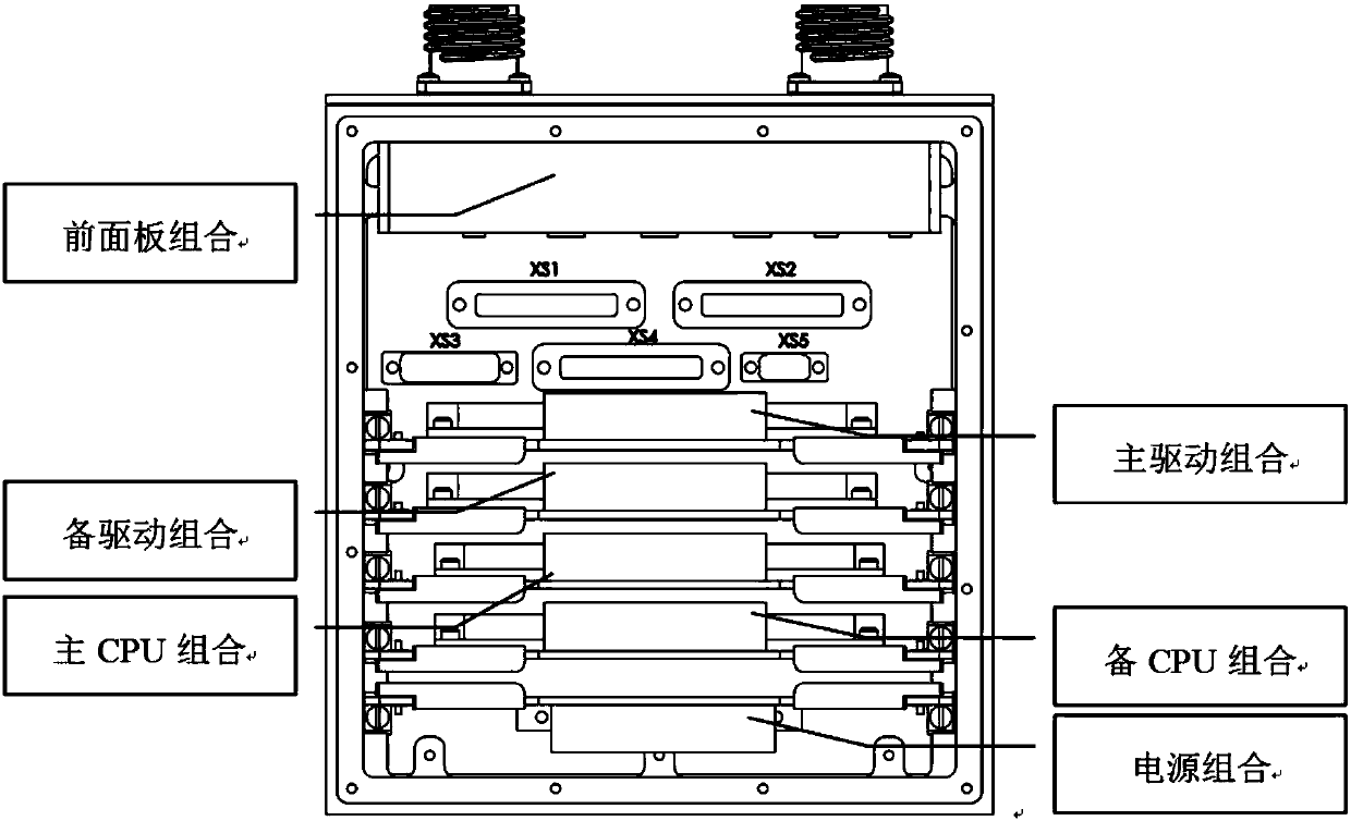
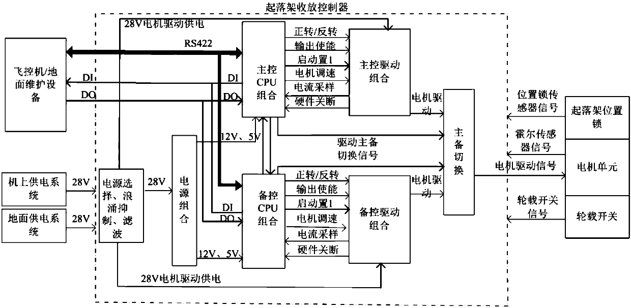
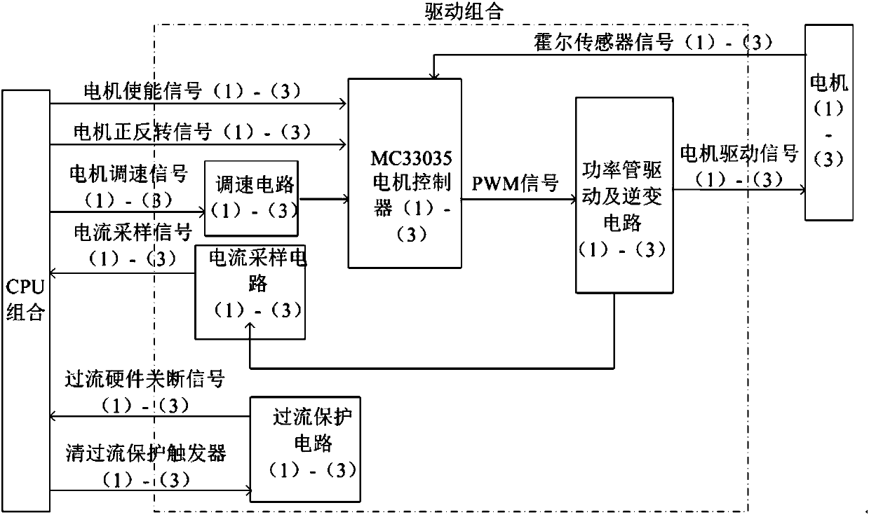
[0019] refer to figure 1 , figure 2 . In the embodiments described below, a multi-redundancy landing gear electric retractable controller is composed of a chassis structure and 6 electronic components. The chassis structure includes a front panel module, a bottom plate combination, and an upper cover plate combination, and the front panel module is used for power supply selection, surge suppression, filtering, and main and standby channel switching. The electronic components include: a main control CPU combination module, a backup control CPU combination module, a main control drive combination module, a backup control drive combination module, a master / standby switching module, a power supply combination module and a motherboard combination module. The power combination module, the main control CPU combination module, the backup control CPU combination module, the main control drive combination module, the backup control drive combination module and the master / standby swit...


PUM


Abstract

The invention discloses a multi-redundancy landing gear electric retraction controller, and aims to provide a controller with light weight, small size, good reliability and strong environmental adaptability. According to the technical scheme, a main control CPU combination module is connected with a standby control CPU combination module and is correspondingly connected with a main control drivingcombination module and a standby control driving combination module through forward rotation and reverse rotation, output enabling, start setting 1, motor speed regulation, current sampling and hardware cut-off control lines respectively; the main control CPU combination module and the standby control CUP combination module are connected with a switching module and a standby switching module through driving main and standby control switching signal lines and a motor driving control line; the main and standby switching modules are connected with a landing gear motor unit through the motor driving signal line; the main control CPU combination module receives a landing gear retraction command, controls logic processing and sends a motor control command; the main control driving combinationmodule and the standby control driving combination module receive motor control commands of the main control CPU combination module and standby control CPU combination module and a motor Hall sensor signal.

Description

technical field [0001] The invention relates to a landing gear retractable controller, in particular to an electric landing gear retractable controller for an unmanned aerial vehicle. Background technique [0002] The traditional aircraft landing gear retractable actuator is driven by the centralized hydraulic source of the aircraft. The long hydraulic pipeline connects the hydraulic components and the hydraulic actuator with various functions to drive each part to move. However, when the hydraulic accessories work, there are Leakage and pressure loss along the pipeline, and the throttle valve is required to adjust the movement speed when the landing gear is actuated. A large amount of energy is consumed in the form of leakage, pipeline loss and throttling heat generation. The energy utilization rate is low; at the same time, the hydraulic system includes not only power hydraulic components, but also corresponding hydraulic control components, hydraulic actuators and complex...

Claims


Application Information

Patent Timeline
IPC IPC(8): B64C25/26B64C25/24G05B9/03
Inventor 陈永李建勇江永泽张文阳何平王元新
Owner CHENGDU KAITIAN ELECTRONICS
Why Eureka
Try Eureka