Piston braking system and braking method thereof

A braking system and piston technology, applied in the direction of brake actuators, gear shifting mechanisms, mechanical equipment, etc., can solve the problem of inability to completely cure brake wear and slip failure, and achieve the goal of increasing mutual friction and achieving stable braking. Effect

Pending Publication Date: 2019-05-31
甘泉龙
View PDF0 Cites 4 Cited by
  • Summary
  • Abstract
  • Description
  • Claims
  • Application Information

AI Technical Summary

Problems solved by technology

[0003] The purpose of the present invention is to provide a piston braking system and a braking method thereof to solve the problem that the braking methods in the prior art convert kinetic energy into internal energy through friction, which cannot completely solve the problem of slipping failure caused by brake wear. To achieve the goal of breaking the shackles of the existing technology and eliminating brake failure caused by friction damage

Method used


Image

  • Piston braking system and braking method thereof
  • Piston braking system and braking method thereof
  • Piston braking system and braking method thereof

Examples


Embodiment 1

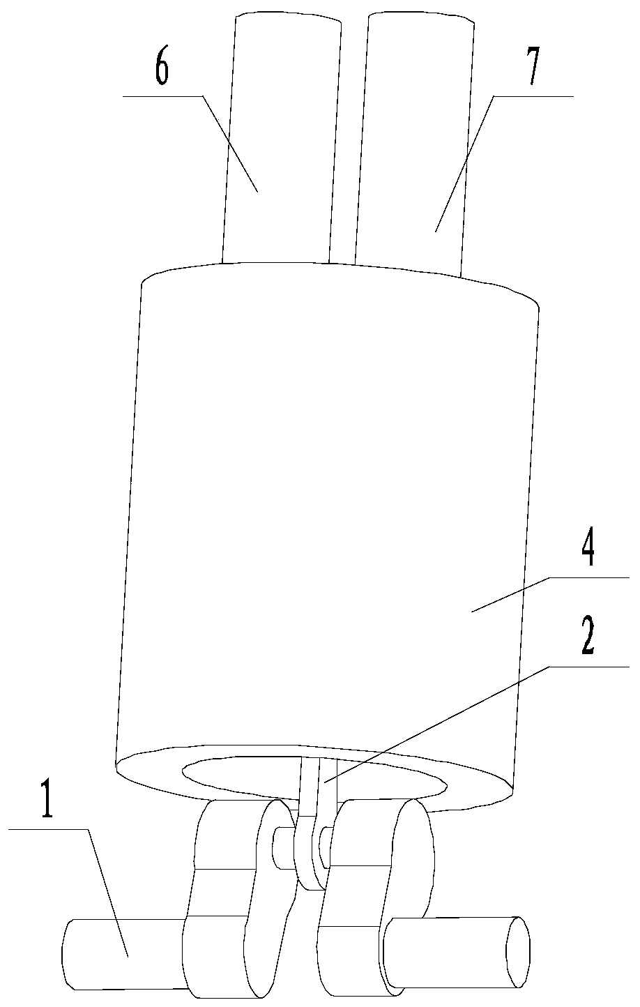
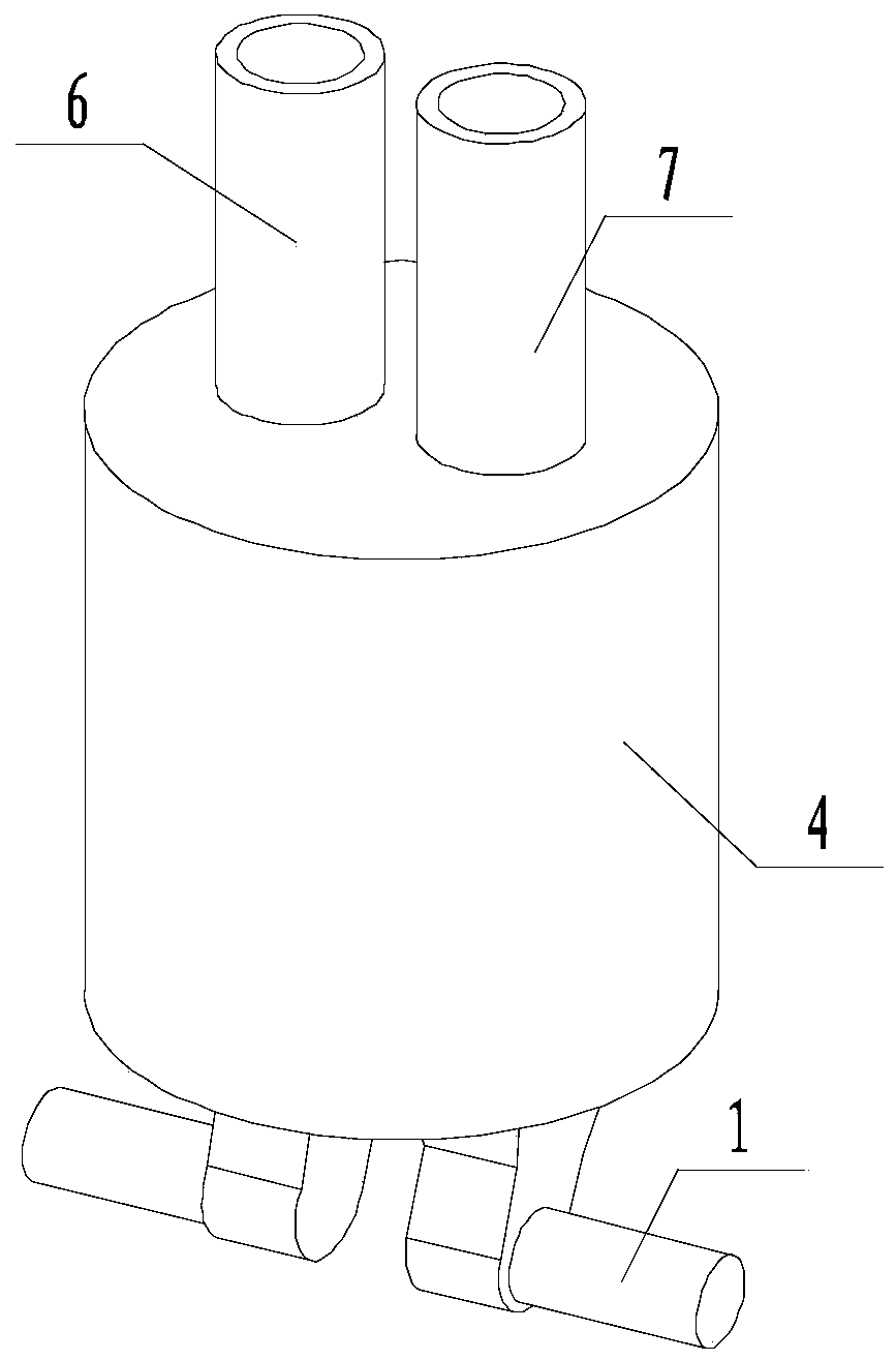
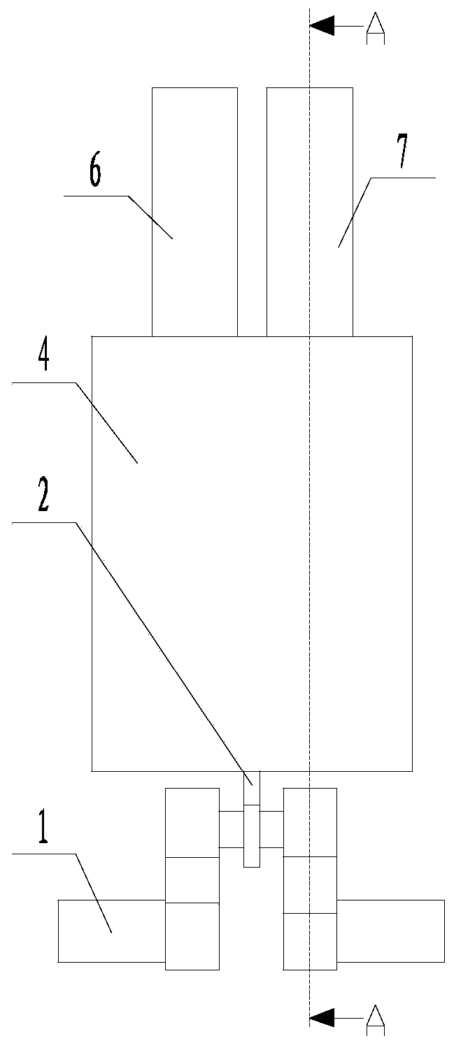
[0042] Such as Figure 1 to Figure 6 The piston brake system shown includes a transmission shaft 1 located between the starting part and the working part, and also includes a piston 3 connected to the transmission shaft 1. When the transmission shaft 1 rotates, it drives the piston 3 in the cylinder liner 4 Performing linear reciprocating motion, a pressure regulating chamber 5 is formed between the piston 3 and the cylinder liner 4, and a pressure regulating mechanism for regulating the pressure in the pressure regulating chamber 5 is also included. The pressure regulating mechanism includes an inlet pipe 6 and a discharge pipe 7 communicating with the pressure regulating chamber 5. A one-way valve 8 communicating with the pressure regulating chamber 5 is arranged in the inlet pipe 6. A one-way valve 8 communicating in a direction away from the pressure regulating chamber 5 is provided, and a regulating valve 9 is also provided in the discharge pipe 7 . The piston rod 2 of t...

Embodiment 2

[0048] Such as Figure 1 to Figure 7 In the piston braking system shown, on the basis of Embodiment 1, the pressure regulating mechanism further includes an oil cylinder 10 connected to the inlet pipe 6 and the outlet pipe 7, and the oil cylinder 10 contains hydraulic oil. The inlet pipe 6 is connected to the bottom of the oil cylinder 10; within the stroke range of the piston 3, the highest liquid level of the hydraulic oil in the oil cylinder 10 is lower than the height of the joint between the discharge pipe 7 and the oil cylinder 10. It also includes a bypass pipe 11, a bypass valve 12 is arranged on the bypass pipe 11, a regulating valve 9 is also arranged in the inlet pipe 6, and one end of the bypass pipe 11 is connected to the one-way valve 8 in the inlet pipe 6 and Between the regulating valves 9 , the other end is connected to the oil cylinder 10 ; within the travel range of the piston 3 , the maximum liquid level of the hydraulic oil in the oil cylinder 10 is lower ...

Embodiment 3

[0053] Such as Figure 1 to Figure 9 In the piston brake system shown, two pistons 3 connected to the transmission shaft 1 form a piston group; when the transmission shaft 1 rotates, the volumes of the two pressure regulating chambers 5 in the piston group always increase one by one. One is large, the other is small. It also includes a pressure sensor located in the pressure regulating chamber 5, and the pressure regulating mechanism adjusts the pressure in the pressure regulating chamber 5 according to the monitoring information of the pressure sensor.


PUM


Abstract

The invention discloses a piston braking system and a braking method thereof. The piston braking system comprises transmission rotating shafts located between a starting component and a working component, pistons, and a pressure adjusting mechanism, wherein each piston is connected with the corresponding transmission rotating shaft; when each transmission rotating shaft rotates, the correspondingpiston is driven to be in straight reciprocating motion in a cylinder jacket; a pressure adjusting cavity is formed between each piston and the cylinder jacket; the pressure adjusting mechanism is used for adjusting the pressure in the pressure adjusting cavities, and comprises an inlet pipe and a discharging pipe, wherein the inlet pipe and the discharging pipe separately communicate with the pressure adjusting cavities; one-way valves are respectively arranged in the inlet pipe and the discharging pipe; and an adjusting valve is also arranged in the discharging pipe. Every time the transmission rotating shafts rotate for a circle, the pistons are driven to make a complete reciprocating motion, and in the process, the volume of each of the pressure adjusting cavities is enlarged and reduced. Through the adoption of the piston braking system disclosed by the invention, the problem that a conventional braking manner adopts a manner that kinetic energy is transformed into internal energythrough friction, so that the condition that wear of brake cannot be thoroughly and radically solved to cause invalid slipping is solved, and the purposes of breaking the shackles in the prior art and stopping braking failure caused by damage of friction are realized.

Description

technical field [0001] The invention relates to the field of braking, in particular to a piston braking system and a braking method thereof. Background technique [0002] Vehicle braking system, also known as braking, refers to the action of stopping or reducing the speed of running locomotives, vehicles and other means of transportation or machinery. The general principle of braking is to fix a wheel or disc on the high-speed shaft of the machine, install a corresponding brake shoe, belt or disc on the machine base, and make it generate braking torque under the action of external force. The brake device is also a mechanical brake device that can slow down the speed of the vehicle, also known as a reducer. To put it simply: the brake pedal of the car is under the steering wheel. If you step on the brake pedal, the brake lever will be linked and pressed, and the brake pads transmitted to the brake drum will block the brake wheel, so that the car will slow down or stop runnin...

Claims


Application Information

Patent Timeline
Patent Type & Authority Applications(China)
IPC IPC(8): F16D65/14F16D121/02F16D125/02
Inventor 甘泉龙
Owner 甘泉龙
Why Eureka
Try Eureka