A multi-gap gear-rotor system test platform

A gear rotor and test platform technology, applied in vibration testing, mechanical component testing, machine/structural component testing, etc., can solve the problems of high manufacturing requirements, high cost, errors, etc., and achieve low processing cost and strong practicability. , the effect of simple structure

Active Publication Date: 2021-01-12
HEBEI UNIV OF TECH
View PDF8 Cites 0 Cited by
  • Summary
  • Abstract
  • Description
  • Claims
  • Application Information

AI Technical Summary

Problems solved by technology

[0003] As disclosed in the previous research results of the inventors (Zhang Huibo, You Bindi, Zhao Yang. Experimental research on the dynamics of gear mechanisms considering multi-gap coupling [J]. Vibration and Shock, 2017,36(21):255-263.) A spur gear external meshing multi-gap test platform, the test platform includes a slider, a drive motor, a bracket, and a driven wheel shaft, the slider is placed in a chute on the bracket, and the slider is along the direction of the center distance between the main and driven gears Move left and right to adjust the center distance of the main and driven gears. In this platform, the motor is directly fixed with the driving gear. The vibration of the motor itself will cause noise to the data, interfere with the real data, and generate errors; at the same time, due to the use of sliders to adjust Tooth side clearance will lead to inaccurate fine control. During the experiment, the clearance of the transmission mechanism is controlled within 300 microns, and the precision requirements are high. This test bench cannot meet the actual precision requirements, and the manufacturing requirements are high and the cost is high.

Method used


Image

  • A multi-gap gear-rotor system test platform
  • A multi-gap gear-rotor system test platform
  • A multi-gap gear-rotor system test platform

Examples


Embodiment 1

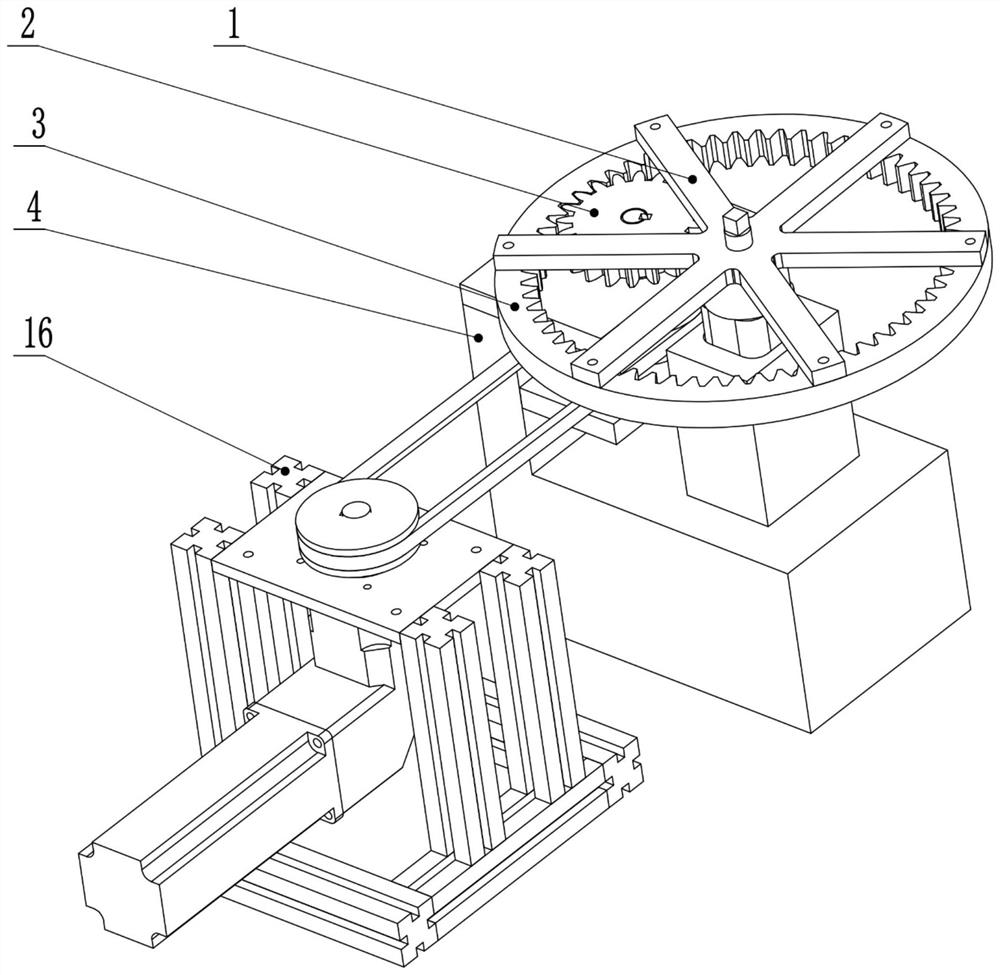
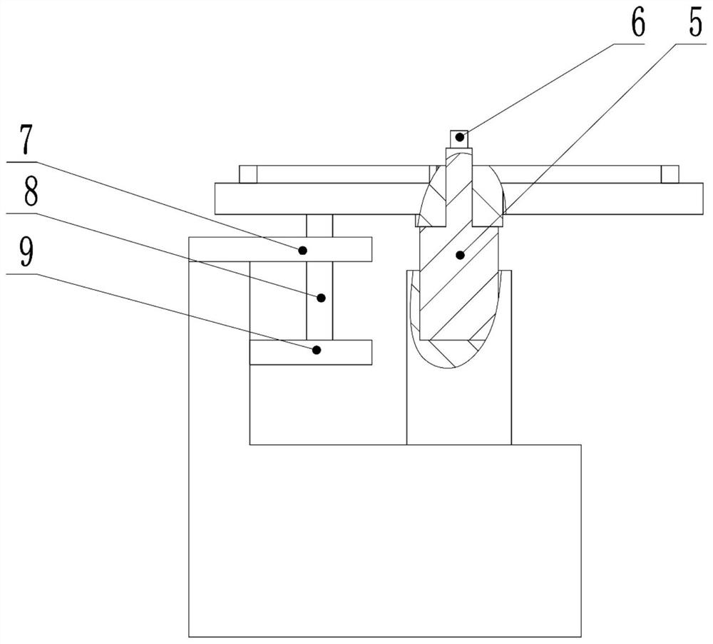
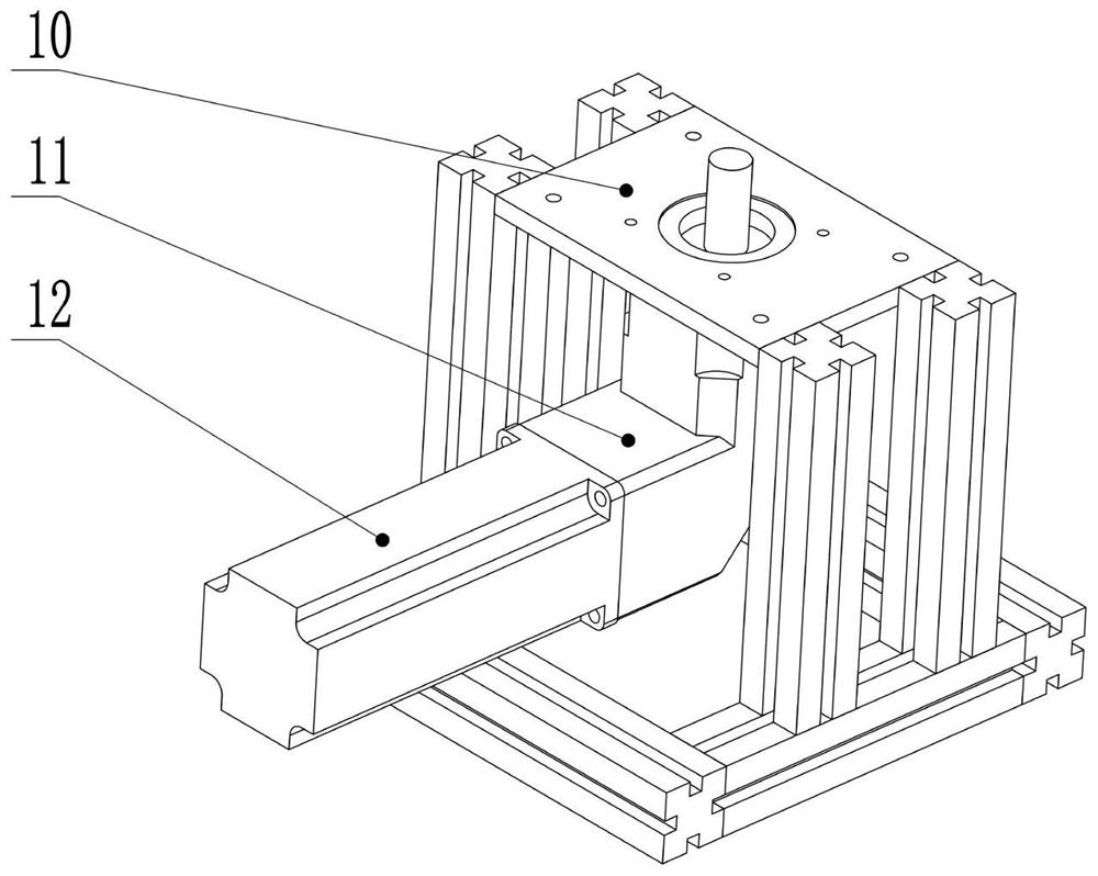
[0044] This embodiment provides a multi-gap internal gear rotor system test platform (see Figure 1-4 , referred to as test platform), including internal gear rotor test bench, driving device and transmission mechanism; said internal gear rotor test bench includes workbench base 4, driven gear frame support block 5, driven gear frame 1, Driven gear 3, upper bearing plate 7, lower bearing plate 9, driving gear shaft 8, driving gear 2 and triaxial acceleration sensor 6;

[0045] The workbench base 4 is L-shaped (see Figure 5 ), the L-shaped horizontal surface is provided with a mounting column for installing the driven gear frame support block, and the upper end of the mounting column is provided with a groove; on the L-shaped vertical surface, the driving gear shaft is fixed by the upper and lower bearing plates; The lower part of the supporting block of the driven gear frame has a shape matching the groove of the mounting column, and is fixed in the groove, and the upper par...


PUM


Abstract

The invention relates to a multi-gap gear rotor system test platform which comprises a driven gear, a driving gear, a work table base, driven gear frame support blocks, a driven gear frame, a three-axis acceleration sensor and a drive device. The work table base is L-shaped. A mounting post used for mounting a driven gear frame support block is arranged on the horizontal surface of the L shape. Agroove is arranged on the upper end of each mounting post. A driving gear shaft is fixed by upper and lower bearing plates on the vertical surface of the L shape. The driving gear is arranged on the upper part of the driving gear shaft. The lower part of each driven gear frame support block matches the groove of a mounting post in shape, and is fixed in the groove. The upper part is a cylinder used for mounting the driven gear. A number of driven gear frame support blocks are arranged, and the radius of the cylindrical parts of a number of driven gear frame support blocks is different. Due tothe driven gear frame support blocks with multiple specifications and precision, the platform has the advantages of more convenient operation, being more precise and lower processing cost.

Description

technical field [0001] The invention relates to the technical field of space transmission mechanism research, in particular to a multi-gap gear rotor system test platform. Background technique [0002] With the development of high-speed and high-precision mechanical engineering, the motion accuracy and operation stability of mechanical systems are required to be higher and higher, and the influence of clearance on the dynamic characteristics of the system has gradually attracted people's attention. However, the previous research objects are relatively simple, and they are basically researched on the single-gap problem. However, there are often multiple or multiple gaps in the mechanisms that are actually used in engineering, such as internal meshing gear transmission mechanisms and external meshing gear transmission mechanisms. These gaps have an effect on system vibration. Therefore, a multi-gap gear-rotor system test platform is needed to meet the research requirements o...

Claims


Application Information

Patent Timeline
Patent Type & Authority Patents(China)
IPC IPC(8): G01M13/021G01M13/028G01M7/02
Inventor 张慧博李广平戴士杰姚金铭张建丰
Owner HEBEI UNIV OF TECH
Why Eureka
Try Eureka