Gas barrier arrangement structure and barrier method used in landfill

A technology for landfill and structure layout, applied in separation methods, chemical instruments and methods, and solid waste removal, etc., can solve the problems of uneven distribution, low cohesion, and high construction costs, and achieve simple construction technology, The effect of short time-consuming and improved safety

Pending Publication Date: 2019-06-07
INST OF ROCK AND SOIL MECHANICS - CHINESE ACAD OF SCI
View PDF7 Cites 2 Cited by
  • Summary
  • Abstract
  • Description
  • Claims
  • Application Information

AI Technical Summary

Problems solved by technology

In the absence of good isolation facilities between the cleaned area and the non-cleaned area, the gas between the two areas is very easy to penetrate each other, and it is very easy to cause safety accidents such as fire or explosion.
[0005] In addition, due to the large pores, uneven distribution and low cohesion of the g

Method used


Image

  • Gas barrier arrangement structure and barrier method used in landfill
  • Gas barrier arrangement structure and barrier method used in landfill
  • Gas barrier arrangement structure and barrier method used in landfill

Examples


Embodiment Construction

[0035] The following will clearly and completely describe the technical solutions in the embodiments of the present invention with reference to the accompanying drawings in the embodiments of the present invention. Obviously, the described embodiments are only some, not all, embodiments of the present invention. Based on the embodiments of the present invention, all other embodiments obtained by persons of ordinary skill in the art without making creative efforts belong to the protection scope of the present invention.

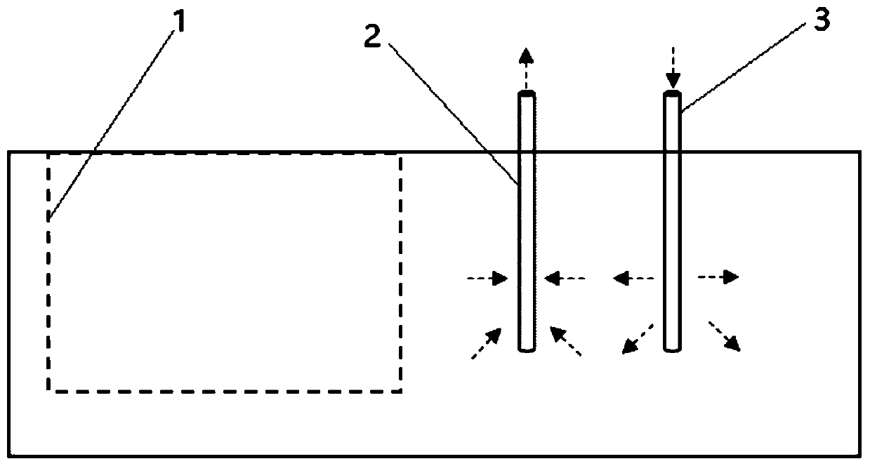
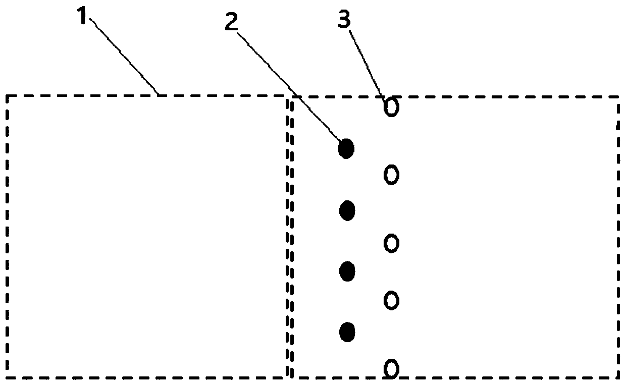
[0036] figure 1 It is a schematic diagram of a gas barrier arrangement structure for a landfill site according to an embodiment of the present invention, figure 2 for figure 1 The schematic diagram of the top view, combined with figure 1 and figure 2 , the barrier arrangement structure includes gas extraction wells 2 and gas injection wells 3, wherein, the gas extraction wells 2 are provided with multiple, and the multiple gas extraction wells 2 are on th...


PUM


Abstract

The invention belongs to the field of environmental geotechnical engineering, and particularly relates to a gas barrier arrangement structure and barrier method used in a landfill. The barrier arrangement structure comprises gas extraction wells and gas injection wells; and a plurality of gas extraction wells are located in a first straight line, the gas injection wells are located in a second straight line, and the first straight line and the second line are far away from a cleaning area in sequence. The barrier method includes the steps of arranging the gas extraction wells and the gas injection wells on a garbage heap outside the cleaning area; and injecting air into the garbage heap by utilizing the gas injection wells, sucking the injected air and methane in the cleaning area into thegas extraction wells through the gas extraction wells, and performing a chemical reaction on oxygen in the air and the methane to reduce the methane in the cleaning area. The gas barrier arrangementstructure and gas barrier method provided by the invention have the characteristics of a simple construction process, short consumed time, low costs and easy maintenance.

Description

technical field [0001] The invention belongs to the field of environmental geotechnical engineering, and in particular relates to a gas barrier arrangement structure and a barrier method for landfill sites. Background technique [0002] With the continuous acceleration of my country's urbanization process, the output of municipal solid waste has increased year by year, and the service life of landfills has gradually shortened. Landfills produce two main pollutants—biogas and leachate. Biogas is a mixture of methane, carbon dioxide, hydrogen sulfide and other gases, and leachate is a high-concentration waste liquid produced after degradation, containing heavy metals, organic matter and high salts. Due to the contradiction between the design planning and operation of the landfill site, pollution accidents of varying degrees and new operational requirements have occurred during the long-term operation of the landfill site. Therefore, some of the landfilled waste dumps need to ...

Claims


Application Information

Patent Timeline
IPC IPC(8): B01D53/76B01D53/72B09B1/00
Inventor 刘磊薛强魏明俐魏建明田宇李琦
Owner INST OF ROCK AND SOIL MECHANICS - CHINESE ACAD OF SCI
Why Eureka
Try Eureka