
Method for predicting residual fatigue life of composite material containing initial delamination damage

A composite material, fatigue life technology, applied in instrumentation, calculation, electrical and digital data processing, etc., can solve the problems of decreased fatigue life, high cost, layer-to-layer debonding, etc. Guaranteed accuracy

Active Publication Date: 2019-06-07
GUANGZHOU UNIVERSITY
View PDF3 Cites 5 Cited by
  • Summary
  • Abstract
  • Description
  • Claims
  • Application Information

AI Technical Summary

Problems solved by technology

At present, there are many related studies on fatigue life prediction of composite materials without initial damage, but for composite materials that already contain initial damage, such as contamination of the prepreg tape during the manufacturing process, or volatilization of the resin during the hot pressing process Local debonding between layers of composite material laminates due to non-discharged substances, or delamination defects inside the composite material due to external impact, etc., such composite materials with initial delamination damage are used in practical applications. Frequently encountered, but little work has been done on the prediction of the remaining fatigue life of composites
Moreover, under the fatigue load of composite materials containing initial defects, the initial delamination damage will accelerate the expansion, resulting in a rapid decline in fatigue life. The existing fatigue life prediction model without initial defects is no longer suitable for this kind of situation. Therefore, it is necessary to Fatigue life prediction for composites with initial delamination damage
[0003]The existing fatigue life prediction technology is mainly aimed at non-damage composite materials, regardless of the initial damage in the composite material, this type of model based on the non-destructive initial state cannot be used for prediction Fatigue life of composites with initial damage Residual fatigue life of composites
[0004] The existing technology mainly predicts the fatigue life through the parameters of residual strength and residual stiffness. First, the measurement of the residual strength and residual stiffness of composite materials cannot be carried out online. The composite components in service are removed and put on the test equipment for measurement; secondly, the measurement of these parameters requires the use of relatively expensive test equipment, such as fatigue testing machines; thirdly, when characterizing the fatigue life by means of residual strength, the Destroying composite material specimens is a destructive testing process. Only one data point can be obtained for one specimen, and the cost of establishing a fatigue life prediction model is relatively high.

Method used


Image

  • Method for predicting residual fatigue life of composite material containing initial delamination damage
  • Method for predicting residual fatigue life of composite material containing initial delamination damage

Examples


Embodiment 1

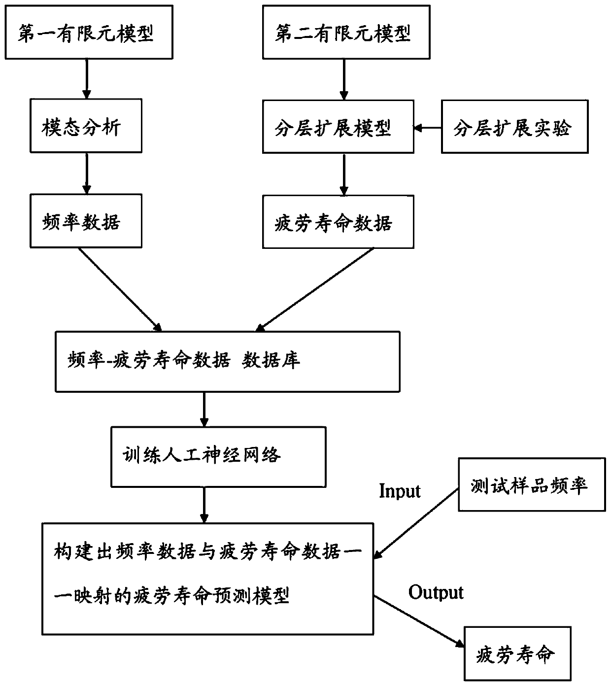
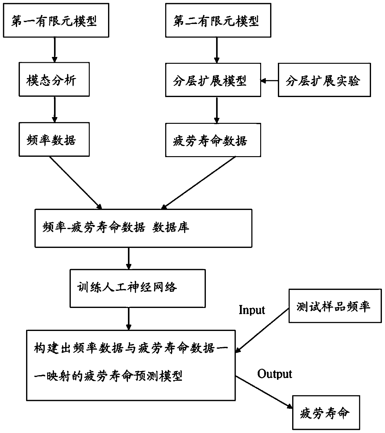
[0038] A method of predicting the remaining fatigue life of a fatigue life composite containing initial delamination damage, the method comprising the steps of:

[0039] (1) Establish a first finite element model of a composite material with initial delamination damage, perform modal analysis, and obtain modal frequency data under initial delamination damage parameters;

[0040] (2) Establish a second finite element model of a composite material containing initial delamination damage, use the empirical parameters of the composite material to construct a delamination expansion model, and then perform stress analysis, and under the stress, use the delamination expansion model for fatigue Delamination extension analysis under load to the failure of the composite material to obtain fatigue life data, the composite material containing initial delamination damage in step (1) is the same as the composite material containing initial delamination damage in step (2);

[0041] (3) Input ...

Embodiment 2

[0048] As an embodiment of the present invention, a system for predicting the remaining fatigue life of a fatigue life composite material containing initial delamination damage composite material, the system includes:

[0049] The first modeling module is used to establish a first finite element model of a composite material containing initial delamination damage, and the first finite element model is used for modal analysis of the structure;

[0050] The first analysis module is used to perform modal analysis through the first finite element model to obtain modal frequency data under initial delamination damage parameters;

[0051] The second modeling module is used to establish a second finite element model of a composite material containing initial delamination damage, the second finite element model is used for delamination expansion analysis, and the second modeling module is the same as the first modeling module Composite materials with initial delamination damage in the...


PUM


Abstract

The invention provides a method for predicting the residual fatigue life of a composite material containing initial delamination damage. According to the method, a modal frequency-residual fatigue life database is used for training an artificial intelligence algorithm, modal frequency is used as input, fatigue life is used as output, and a fatigue life prediction model of one-to-one mapping of frequency data and fatigue life data is constructed; and then the modal frequency of the to-be-measured sample is measured, and the measured frequency is input into the fatigue life prediction model to obtain the residual fatigue life of the composite material laminated plate. According to the method for predicting the residual fatigue life of the composite material containing the initial delamination damage, only vibration equipment needs to be adopted for collecting the frequency, then the fatigue life is predicted, and the method is easy and convenient to implement; online prediction can be carried out, the composite material is not damaged, the cost is low, and compared with other existing fatigue life prediction methods, operation is easy and convenient, and the prediction precision is good..

Description

technical field [0001] The invention relates to the field of fatigue life testing of composite materials, in particular to a method for predicting the remaining fatigue life of composite materials with initial delamination damage. Background technique [0002] Fiber-reinforced composite materials have the advantages of high specific strength, specific modulus, designability, corrosion resistance, etc., and have been widely used in aerospace, construction and civil engineering, energy transportation, marine engineering and other fields. In engineering applications, many fiber-reinforced composite components or components are subjected to repeated alternating loads for a long time during work, and cracks will gradually initiate inside the material. The service life is greatly shortened. At present, there are many related studies on fatigue life prediction of composite materials without initial damage, but for composite materials that already contain initial damage, such as co...

Claims


Application Information

Patent Timeline
Patent Type & Authority Applications(China)
IPC IPC(8): G06F17/50
CPCY02T90/00
Inventor 张芝芳梁智洪廖兴升傅继阳刘爱荣吴玖荣
Owner GUANGZHOU UNIVERSITY
Learn More