Surface emitting laser and surface emitting laser array

A technology of surface-emitting lasers and doped layers, which is applied in the laser field and can solve problems such as the difficulty in growing DBR structures

Active Publication Date: 2019-06-07
CHANGCHUN INST OF OPTICS FINE MECHANICS & PHYSICS CHINESE ACAD OF SCI
View PDF12 Cites 7 Cited by
  • Summary
  • Abstract
  • Description
  • Claims
  • Application Information

AI Technical Summary

Problems solved by technology

Especially in the long wavelength band, due to the problem of material lattice matching, the growth of InP (indium phosphide)-based DBR structure is difficult

Method used


Image

  • Surface emitting laser and surface emitting laser array
  • Surface emitting laser and surface emitting laser array
  • Surface emitting laser and surface emitting laser array

Examples


Embodiment Construction

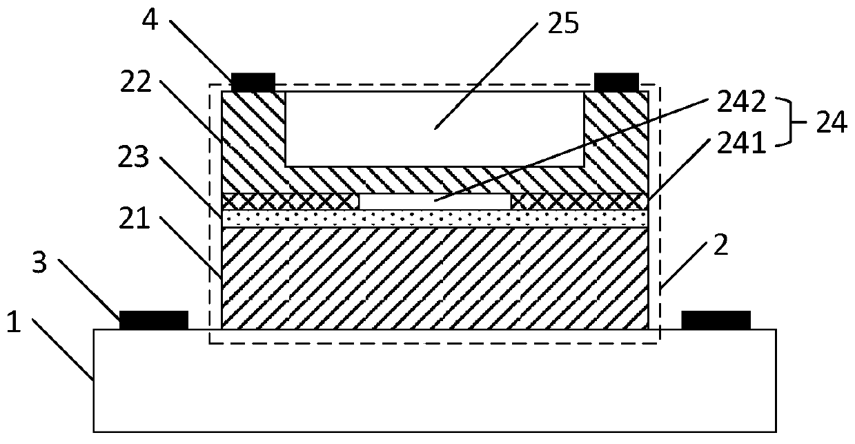
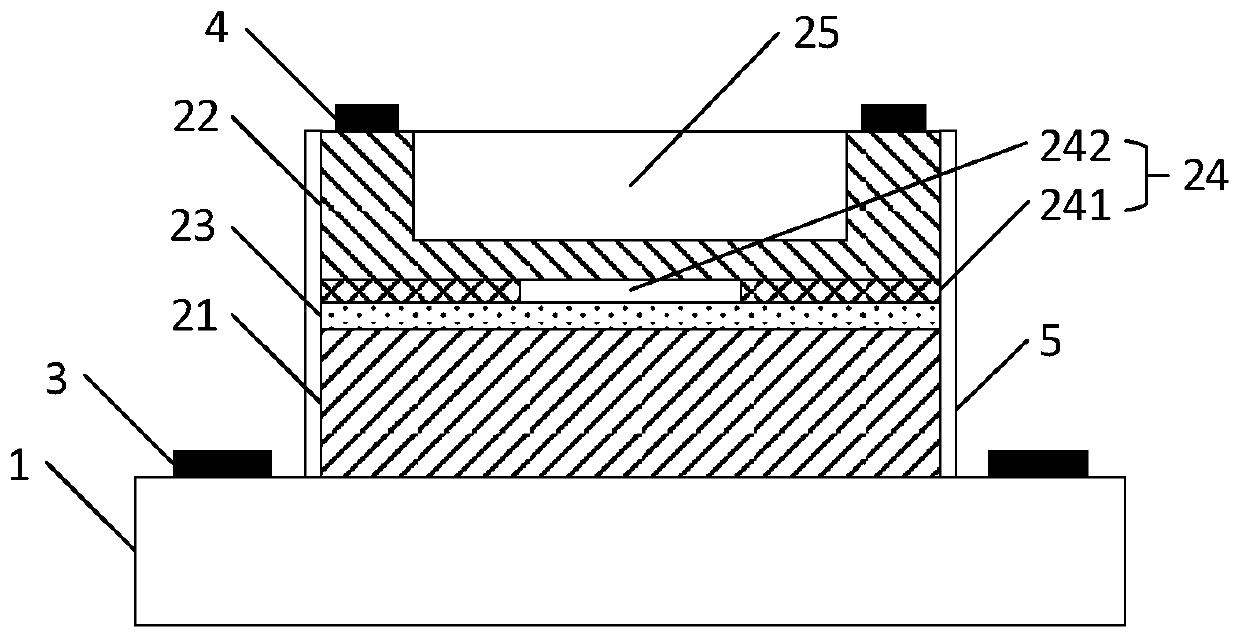
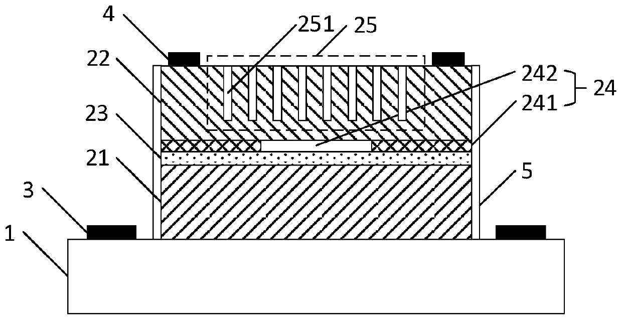
[0029] The core of the present invention is to provide a surface emitting laser. In the prior art, usually the entire active layer is used to emit laser light, and the carrier injection area at this time is the entire surface area of ​​the active layer, resulting in an excessively large carrier injection area. When the same injection current is applied to the outside world, the carrier density is lower, resulting in a larger threshold current required for the active layer to excite photons.

[0030] However, a surface-emitting laser provided by the present invention includes a substrate and a functional layer of a sandwich structure, and the functional layer includes a first doped layer, an active layer, a confinement layer and a second doped layer, wherein the active layer And the confinement layer is located between the first doped layer and the second doped layer. The first doped layer and the second doped layer are used to transport carriers to the active layer, and the c...


PUM


Abstract

The invention discloses a surface emitting laser which comprises a substrate and a functional layer which is of a sandwich-like type structure. The functional layer comprises a first doped layer, an active layer, a limiting layer and a second doped layer, wherein the active layer and the limiting layer are positioned between the first doped layer and the second doped layer. The first doped layer and the second doped layer are used for conveying carriers to the active layer, and the carriers can firstly pass through the limiting layer and then be transmitted to the active layer to compositely emit light. The limiting layer comprises an insulation layer and a conductive column and the conductive column runs through the insulation layer according to a thickness direction, and thus, the carriers need to be transmitted to the active layer through the conductive column, an area of a carrier compounding region of the active region can be limited, and in a case of keeping the same carrier density, a required injection current is smaller, so that in the premise of not changing a volume and an area of photon crystals, a threshold current required for photon excitation is reduced. The invention further provides a surface emitting laser array which also has the beneficial effects above.

Description

technical field [0001] The invention relates to the field of laser technology, in particular to a surface-emitting laser and a surface-emitting laser array. Background technique [0002] Surface-emitting lasers, especially vertical-cavity surface-emitting lasers (VCSELs), have received more and more attention since they were proposed in 1977 due to their advantages such as circularly symmetrical spots, low threshold current, easy two-dimensional integration, and on-surface detection. , are widely used in optical communication, optical interconnection, sensing, optical storage, laser display, laser radar and many other fields. [0003] However, the conventional VCSEL itself has great limitations. First, conventional VCSELs require a complex top-bottom Bragg reflector (DBR) epitaxial growth process, which increases the difficulty and cost of growth. Especially in the long wavelength band, due to the problem of material lattice matching, it is difficult to grow the InP (indiu...

Claims


Application Information

Patent Timeline
Patent Type & Authority Applications(China)
IPC IPC(8): H01S5/183H01S5/187
Inventor 佟存柱王子烨陆寰宇田思聪汪丽杰舒世立张新王立军
Owner CHANGCHUN INST OF OPTICS FINE MECHANICS & PHYSICS CHINESE ACAD OF SCI
Why Eureka
Try Eureka