Laser radar device and laser radar system

A laser radar and laser signal technology, which is applied in the laser field, can solve the problems of laser radar sensitivity reduction, inability to realize monolithic integration, difficulty in achieving high integration, etc., and achieve the effects of improving high collimation, simplifying structure, and low threshold current

Pending Publication Date: 2018-11-16
度亘核芯光电技术(苏州)有限公司
View PDF0 Cites 5 Cited by
  • Summary
  • Abstract
  • Description
  • Claims
  • Application Information

AI Technical Summary

Problems solved by technology

However, 905nm lasers are not an eye-safe LiDAR light source, and edge-emitting lasers have poor beam quality
In addition, the high integration of semiconductor lasers, near-infrared detectors, microlenses, control circuits, and analysis software in all-solid-state lidar is the mainstream direction of lidar. However, in the current all-solid-state lidar, lasers and detectors are independently packaged into modules. , it is impossible to achieve monolithic integration, and it is difficult to achieve high integration
Furthermore, most of the laser beams emitted by the current lidar are divergent, and the proportion of the laser beam actually projected on the target is very small, and the proportion of the laser beam returned to the detector is even smaller, the laser utilization rate is low, and the power consumption is low. Larger, and the sensitivity of the lidar is greatly reduced

Method used


Image

  • Laser radar device and laser radar system
  • Laser radar device and laser radar system
  • Laser radar device and laser radar system

Examples


Embodiment 1

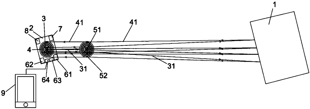
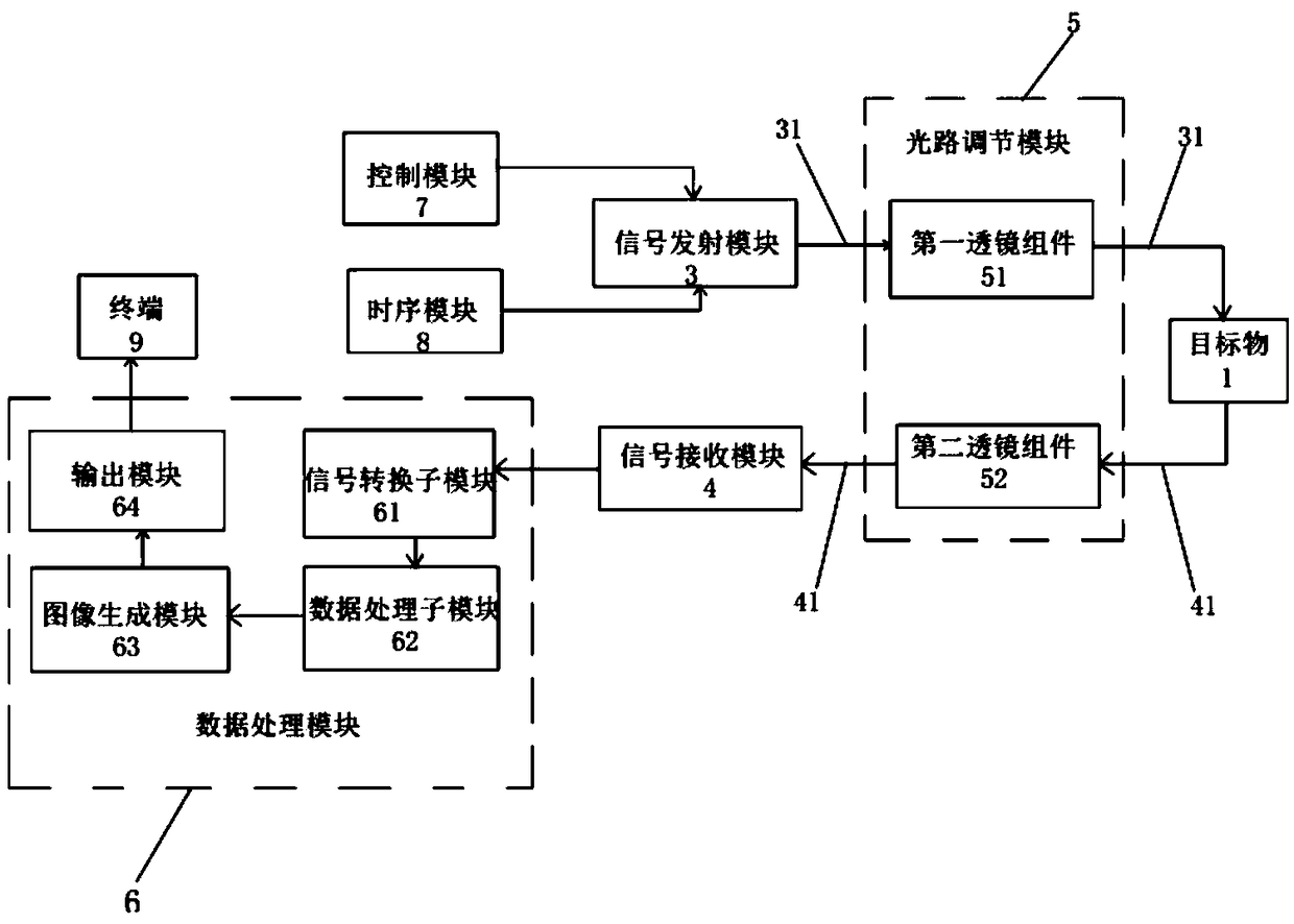
[0051] An embodiment of the present invention provides a laser radar device, such as figure 1 with figure 2 As shown, it includes a signal transmitting module 3, a signal receiving module 4, an optical path adjustment module 5 and a data processing module 6. in,

[0052] The signal transmitting module 3 is used to transmit the laser signal to the target object 1; the signal receiving module 4 and the signal transmitting module 3 are integrated on the same laser radar main board 2, and is used to receive the laser signal reflected back by the target object 1; the optical path adjustment module 5 is arranged on the laser The optical path where the signal is located is used to adjust the optical path of the laser; the data processing module 6 is connected to the signal receiving module 4 and is used to analyze and process the laser signal reflected back from the target object 1 .

[0053] It should be noted that the optical path where the laser signal is located refers to the ...

Embodiment 2

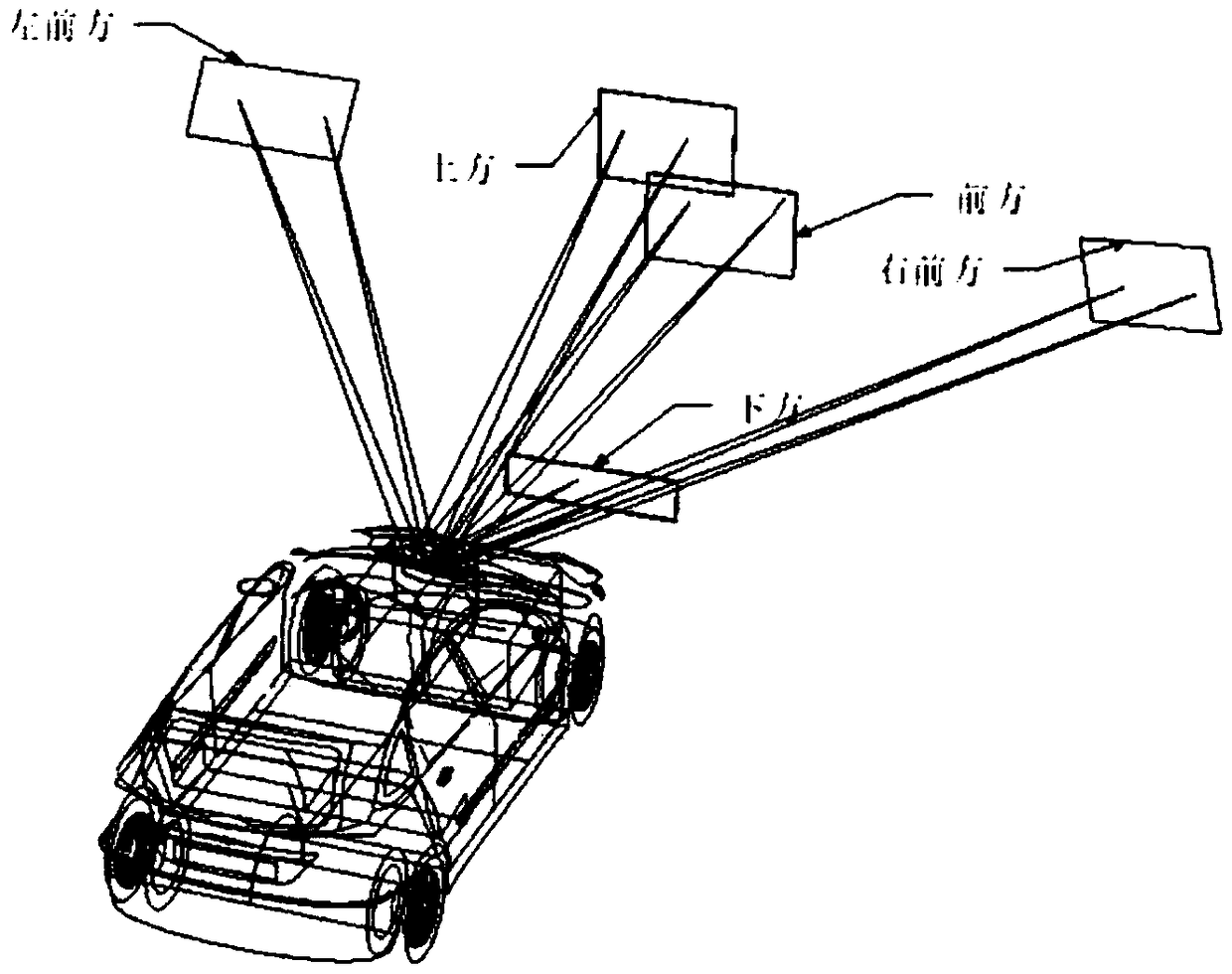
[0080] An embodiment of the present invention provides a laser radar system, including the laser radar device provided in Embodiment 1 and a scanning control device, and the scanning control device is connected to the laser radar device. The scanning control device is used to adjust the deflection direction of the lidar device. In this embodiment, the scanning control device is preferably a small motor, and the deflection direction of the lidar device is finely adjusted by the small motor. As a result, the laser radar device can emit laser light in different directions to realize the scanning function, and can detect and identify road conditions and surrounding environments in a wide range.

[0081] Such as image 3 As shown, the deflection of the laser radar device is controlled by the scanning control device to realize the scanning of various positions such as the front, left front, right front, top, and bottom of the vehicle, and then realize large-scale detection and iden...


PUM


Abstract

The invention relates to the technical field of laser, and discloses a laser radar device. The laser radar device comprises a signal transmitting module, a signal receiving module, an optical path adjusting module and a data processing module, wherein the signal transmitting module is used for transmitting a laser signal to a target object; the signal receiving module is integrated with the signaltransmitting module on the same laser radar main board, and is used for receiving the laser signal reflected by the target object; the optical path adjusting module is arranged on an optical path inwhich the laser signal locates, and is used for adjusting the optical path of laser; and the data processing module is connected with the signal receiving module, and is used for analyzing and processing the laser signal reflected by the target object. The signal transmitting module is a vertical cavity surface emitting laser (VCSEL) array. The signal transmitting module and the signal receiving module are integrated on the same laser radar main board, thereby greatly simplifying the structure of the laser radar device, reducing the size of the existing laser radar device, improving the integration degree, and conforming to the trend of miniaturization of the current laser radar.

Description

technical field [0001] The invention relates to the field of laser technology, in particular to a laser radar device and a laser radar system based on a vertical cavity surface emitting laser. Background technique [0002] Lidar (LiDAR) is growing rapidly in the field of automotive autonomous driving, mainly by using a 905nm semiconductor laser in the near-infrared band to emit laser pulses, and then using a silicon-based avalanche photodetector (APD) to collect reflected light signals to create a sense of the surrounding environment of the car. Point cloud map to realize autonomous navigation and assisted driving. [0003] The famous Velodyne company in the United States has mechanical fast-scanning lidars with three specifications of 16, 32, and 64 lines. Among them, the highest specification 64-line lidar has a measurement range of 120m and a measurement accuracy of about 20mm, but its price is even as high as 75,000 U.S. dollars, which are very expensive and bulky, cann...

Claims


Application Information

Patent Timeline
Patent Type & Authority Applications(China)
IPC IPC(8): G01S7/481G01S7/484G01S7/486
CPCG01S7/4817G01S7/4811G01S7/484G01S7/4863G01S7/4868
Inventor 杨晓杰宋院鑫杨国文赵卫东
Owner 度亘核芯光电技术(苏州)有限公司
Why Eureka
Try Eureka