Moving-magnetic magnetic suspension permanent magnet synchronous planar motor

A permanent magnet synchronous, planar motor technology, applied in the direction of magnetic circuit shape/style/structure, electrical components, electromechanical devices, etc., to achieve the effects of simplified motor structure, high precision, and improved positioning accuracy

Inactive Publication Date: 2019-06-07
HARBIN INST OF TECH
View PDF5 Cites 4 Cited by
  • Summary
  • Abstract
  • Description
  • Claims
  • Application Information

AI Technical Summary

Problems solved by technology

[0007] The purpose of the present invention is to solve the problem of how to take into account both simple structure and high positioning accuracy. The present invention provides a moving magnet magnetic levitation permanent magnet synchronous planar motor

Method used


Image

  • Moving-magnetic magnetic suspension permanent magnet synchronous planar motor
  • Moving-magnetic magnetic suspension permanent magnet synchronous planar motor
  • Moving-magnetic magnetic suspension permanent magnet synchronous planar motor

Examples


Embodiment Construction

[0039] The following will clearly and completely describe the technical solutions in the embodiments of the present invention with reference to the accompanying drawings in the embodiments of the present invention. Obviously, the described embodiments are only some, not all, embodiments of the present invention. Based on the embodiments of the present invention, all other embodiments obtained by persons of ordinary skill in the art without making creative efforts belong to the protection scope of the present invention.

[0040] It should be noted that, in the case of no conflict, the embodiments of the present invention and the features in the embodiments can be combined with each other.

[0041] The present invention will be further described below in conjunction with the accompanying drawings and specific embodiments, but not as a limitation of the present invention.

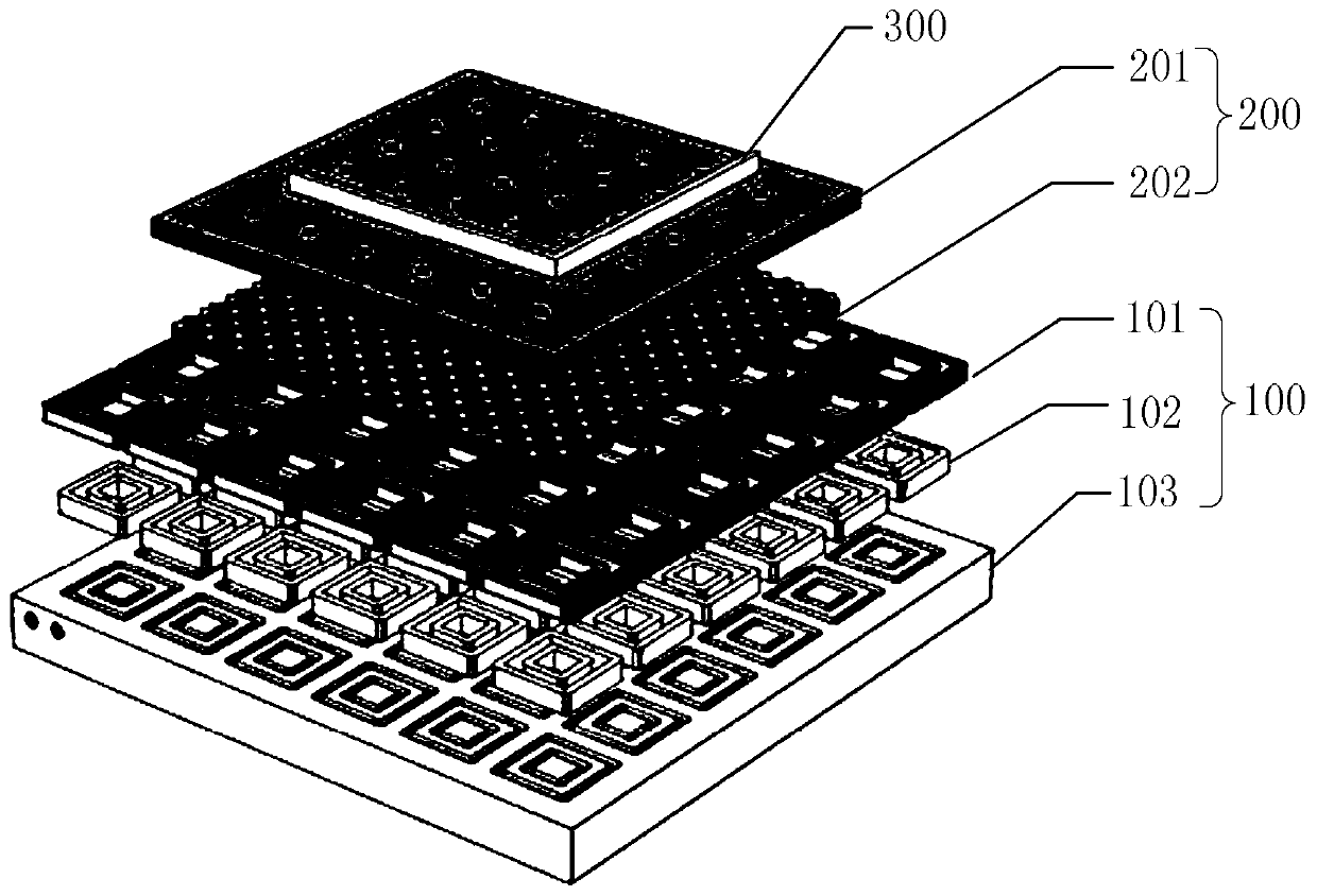
[0042] see figure 1 To illustrate this embodiment, the moving magnet type magnetic levitation permanent ma...


PUM


Abstract

The invention discloses a moving-magnetic magnetic suspension permanent magnet synchronous planar motor, relates to a multiphase moving-magnetic magnetic suspension permanent magnet synchronous planarmotor, and belongs to the field of motors. The problem of how to give consideration to simple structure and high locating accuracy at the same time is solved. The moving-magnetic magnetic suspensionpermanent magnet synchronous planar motor includes a stator and a rotor, and air gaps exist between the stator and the rotor; magnetic levitation supporting is conducted on the rotor by the stator, and interaction of the stator and the rotor directly covert electromagnetic energy between the stator and the rotor into two-dimension planar motion of the rotor. The moving-magnetic magnetic suspensionpermanent magnet synchronous planar motor is mainly applied to modern precision and ultra-precision machining devices of precision machining, semiconductor electronic chip producing and the like.

Description

technical field [0001] The invention relates to a multi-phase moving magnet type magnetic levitation permanent magnet synchronous planar motor, which belongs to the field of motors. Background technique [0002] Modern precision and ultra-precision processing equipment has an urgent need for high-response, high-speed, high-precision two-dimensional planar drive devices, such as precision machining, semiconductor electronic chip production, mechanical loading and unloading, manufacturing automated instruments and even robot drives. [0003] The traditional two-dimensional planar driving device is usually superimposed by two sets of linear motion conversion mechanisms driven by rotating motors. Due to the complex structure of the linear motion conversion device (usually a screw-nut mechanism), the transmission accuracy and speed are subject to certain constraints. Constraints, and there are a series of problems such as friction, backlash, deformation, etc., making it difficult...

Claims


Application Information

Patent Timeline
IPC IPC(8): H02K41/03H02K1/06H02K3/28H02N15/00
Inventor 张鲁寇宝泉葛庆稳周峰李熙伦
Owner HARBIN INST OF TECH
Why Eureka
Try Eureka