
Radial-axial bidirectional hybrid magnetic circuit frameless permanent magnet synchronous motor

A hybrid magnetic circuit and permanent magnet motor technology, applied to synchronous motors with stationary armatures and rotating magnets, synchronous machines, magnetic circuits, etc., can solve the problem of increasing copper loss and cannot meet the needs of direct drive tanks or self-propelled artillery turrets Horizontal rotation, complex structure and other issues, to achieve the effect of reducing copper consumption, small space, and simple motor structure

Inactive Publication Date: 2020-08-14
NANJING UNIV OF SCI & TECH
View PDF8 Cites 0 Cited by
  • Summary
  • Abstract
  • Description
  • Claims
  • Application Information

AI Technical Summary

Problems solved by technology

But in these two kinds of motors, the armature winding has separate radial and axial parts, which not only increases the copper loss but also makes the structure slightly complicated, and because the middle of the connection between the turret of the tank or self-propelled gun and the car body below needs to be Leave space for people to enter and exit, so the above two motor structures cannot meet the requirements of directly driving the horizontal rotation of tanks or self-propelled artillery turrets, and further improvement is still needed

Method used


Image

  • Radial-axial bidirectional hybrid magnetic circuit frameless permanent magnet synchronous motor
  • Radial-axial bidirectional hybrid magnetic circuit frameless permanent magnet synchronous motor
  • Radial-axial bidirectional hybrid magnetic circuit frameless permanent magnet synchronous motor

Examples


Embodiment

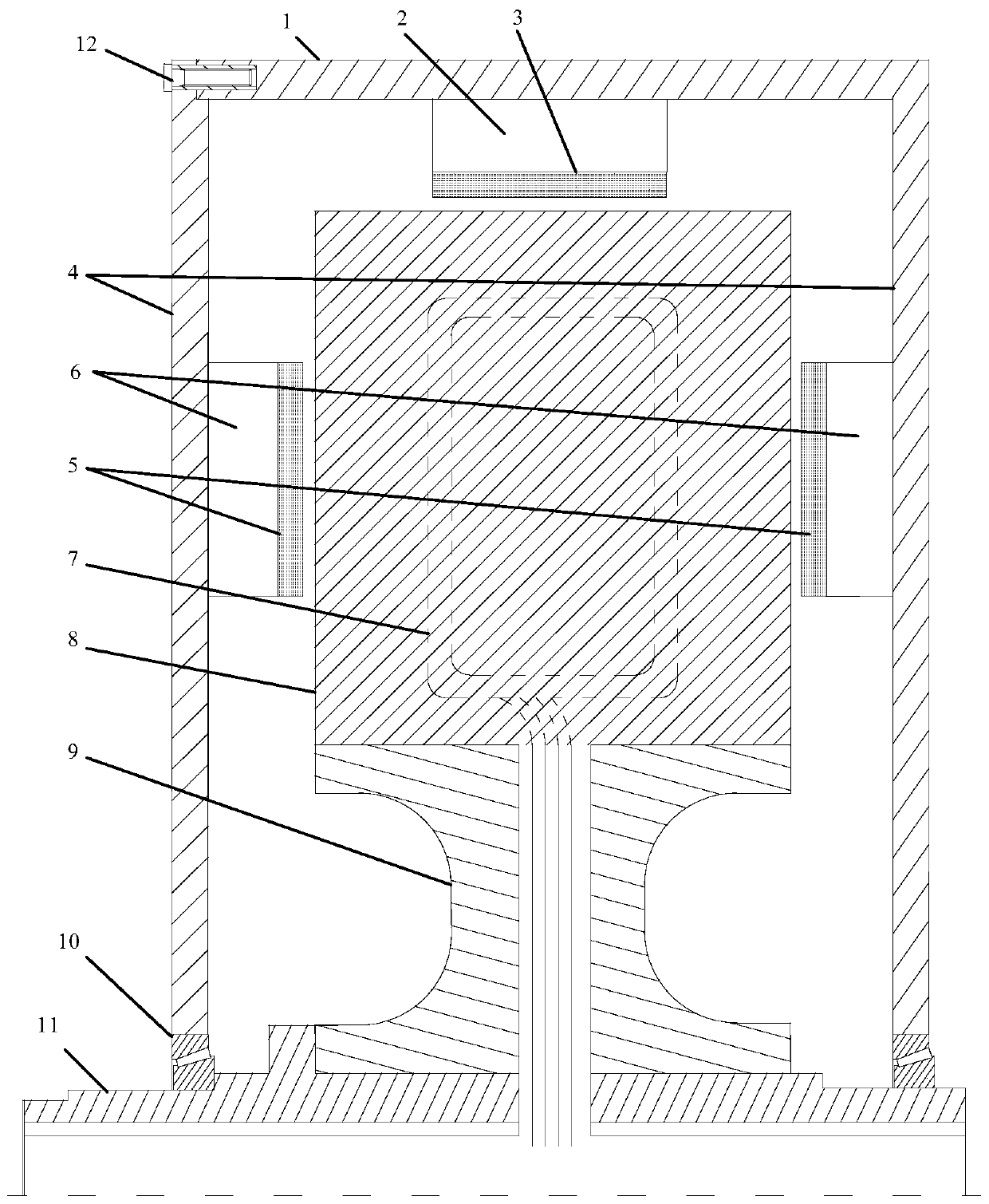
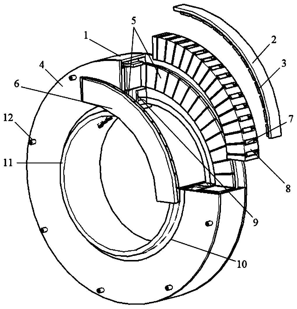
[0034] The radial-axis bidirectional hybrid magnetic circuit frameless permanent magnet motor of the present invention includes a stator and an inverted U-shaped rotor, wherein the stator part includes a stator core 8 and an armature winding 7, and the inverted U-shaped rotor includes a radial part and an axial part, the former Comprising a back yoke 2 in the shape of a thin cylinder, an outer casing 1 and a permanent magnet 3, the latter having two axial sides each containing a disc-shaped back yoke 6, an end cap 4 and a permanent magnet 5;

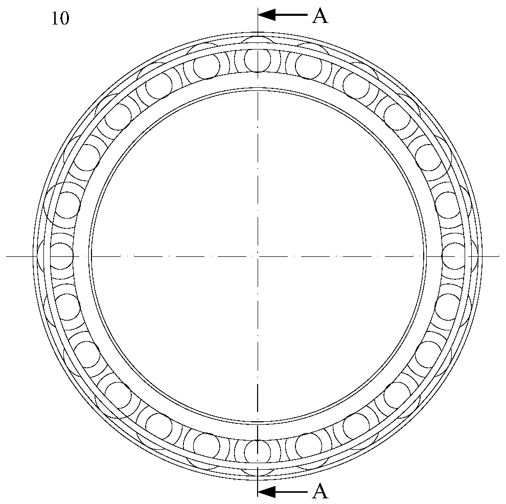
[0035] The stator part is between the disk-shaped back yokes 6 on both sides of the axial direction, and there are end covers 4 on the outer sides of both axial sides, and the end covers 4 on both axial sides and the radial outer casing 1 are closed as a A cavity, the stator part and the inverted U-shaped rotor are installed in the cavity, and the whole is set on the shaft wall of the hollow shaft 11;

[0036] A radial air gap is formed ...


PUM


Abstract

The invention discloses a radial-axial bidirectional hybrid magnetic circuit frameless structure permanent magnet motor. The motor comprises an outer casing, a radial back yoke, a radial permanent magnet, an end cover, an axial permanent magnet, an axial back yoke, an armature winding, a stator core, a support member, a bearing, a hollow shaft and a screw. The armature winding is embedded into a groove of the stator core, the stator core is installed in the periphery of the hollow shaft, the hollow shaft is connected with the end cover through the bearing, the axial back yoke is arranged in the middle of the end cover, and the axial permanent magnet is installed on the inner side surface of the axial back yoke. The outer casing is arranged at the top of the end cover; the radial back yokeis arranged in the middle of the outer casing; the radial permanent magnet is installed on the surface of the inner side of the radial back yoke in the circumferential direction, in the radial permanent magnet array and the axial permanent magnet array, the adjacent permanent magnets are alternately arranged in the N-pole direction and the S-pole direction, N and S poles in any pair at the two sides in the axial direction are correspondingly arranged in the axial direction, and therefore a closed magnetic potential forward series magnetic flux loop is formed in the radial direction and the axial direction. According to the invention, the torque density, the power density and the energy efficiency of the motor are improved.

Description

technical field [0001] The invention relates to the technical field of low-speed and high-torque direct-drive permanent magnet motors, in particular to a radial-axis bidirectional hybrid magnetic circuit frameless permanent magnet motor. Background technique [0002] There is a class of motor-driven objects in military and civilian use that has the characteristics of large inertia, high torque and low speed, such as the horizontal movement of tanks and self-propelled artillery turrets, the horizontal movement of crane seats and large rotating platforms. The traditional electric driving method adopts the driving form of "driving motor + reducer". The rated torque of the motor is also far lower than the torque of several thousand Nm required to drag the above-mentioned driving objects, so it is necessary to reduce the speed and increase the torque through a matching reducer. However, due to the introduction of the reducer, there will inevitably be transmission gaps and elasti...

Claims


Application Information

Patent Timeline
IPC IPC(8): H02K1/27H02K1/16H02K7/00H02K21/22
CPCH02K1/16H02K1/165H02K1/2786H02K7/003H02K21/227H02K2201/03
Inventor 耿伟伟李强孙乐汪诚蒋雪峰余剑
Owner NANJING UNIV OF SCI & TECH
Learn More