
Integrated pump and motor

a technology of integrated pumps and motors, which is applied in the direction of positive displacement liquid engines, pumping cylinders, machines/engines, etc., can solve the problems of not allowing vibration-free operation of pumps and not allowing quiet operation, so as to reduce the parts count of the overall device, simplify the motor construction, and reduce the effect of overall device parts coun

Inactive Publication Date: 2008-10-23
HOFFMAN LESLIE +1
View PDF3 Cites 5 Cited by
  • Summary
  • Abstract
  • Description
  • Claims
  • Application Information

AI Technical Summary

Benefits of technology

[0006]In contrast to the existing architecture for small pumps the present invention incorporates at least a portion of the motor assembly into the frame of the pump assembly simplifying motor construction and reducing the parts count of the overall device. This form of assembly also permits more accurate location and alignment of the reciprocating assembly, which is advantageous. In addition to the integration of motor elements into the pump frame, the reciprocating piston is balanced by an eccentric balancing construction that provide better “balance” or dampening of vibration modes in the device. This counter-weighted assembly addresses vibration modes and produces a pump that is quieter and smoother in operation, which is desirable in most applications.

Problems solved by technology

Even when the pumps are of modest size the piston assembly forms a dynamically unbalanced element in the construction and efforts are made in the prior art to eliminate some vibration modes from the system.
Although such a system is an advantage over an unbalanced assembly it does not permit vibration free operation of the pumps nor does it permit quiet operation.

Method used


Image

  • Integrated pump and motor
  • Integrated pump and motor
  • Integrated pump and motor

Examples


Embodiment Construction

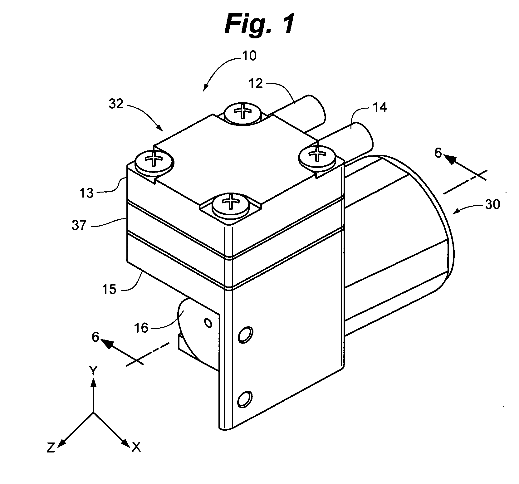
[0014]FIG. 1 shows the general layout of the motor / pump assembly 10. The pump portion is generally designated 32 while the motor portion is generally designated 30. In operation DC current is supplied to the motor and it drives the pump. Air is admitted through port 12 and emitted from port 14.

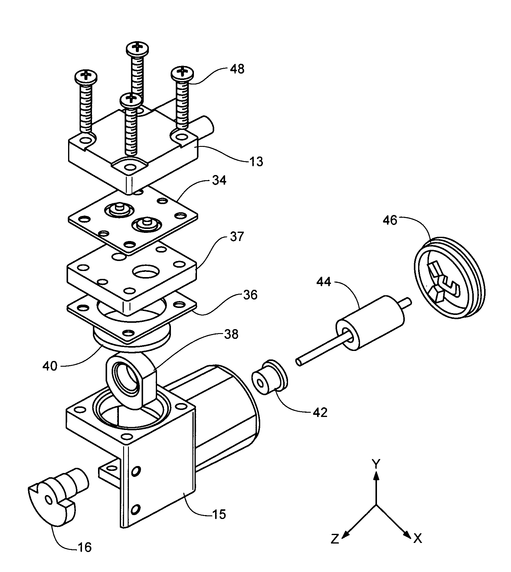
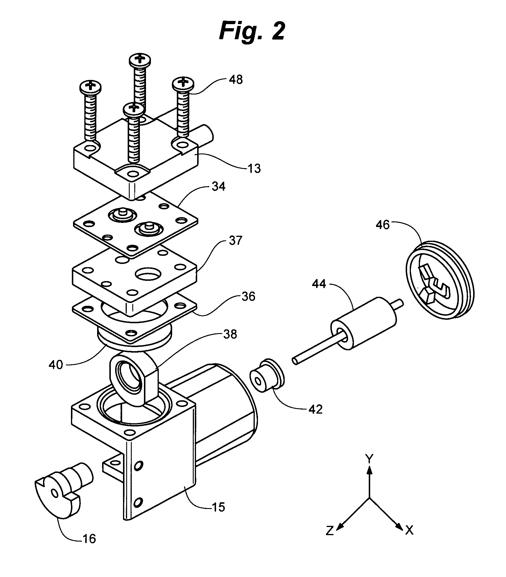
[0015]FIG. 2 shows the assembly 10 exploded to show the individual components. The pump portion includes the cylinder head 13, which sandwiches the flap valve sheet 34 between the cylinder head 13 and the cylinder plate 37. Screws typified by screw 48 holds the cylinder head valve plate 24 and cylinder to the to the motor / pump frame 15. The connecting rod / piston 38 is positioned in to the cylinder.

[0016]FIG. 3 shows the motor / pump frame 15 in isolation. FIG. 4 is a cross-section of the motor / pump frame 15 showing the stator assembly 56 that is placed in the mold and molded into position in the motor / pump frame 15. In the figure the axial motor shaft 20 is shown in isolation intersecting at 90°...


PUM


Abstract

An integrated motor pump for use in medical devices and the like.

Description

CROSS REFERENCE TO RELATED APPLICATION[0001]This application claims the benefit of U.S. Provisional Application Ser. No. 60 / 793,508, filed Apr. 20, 2006.FIELD OF THE INVENTION[0002]The present invention relates generally to small pumps for moving air and other gases. The low pressure pump uses a brushless DC motor to drive a reciprocating air pump. This type of device is used in various applications including medical devices such as automatic blood pressure monitoring devices where the pump inflates the blood pressure cuff.BACKGROUND OF THE INVENTION[0003]Small motor driven reciprocating air pumps have been widely used for a variety of application and are typically used for sampling gases or inflating blood pressure measuring cuffs in the medical device field. The availability and advent of brushless DC motors have made such pumps very controllable, reliable and safe and which has greatly increased their use in the field.[0004]In pumps of the prior art design the pump includes a pum...

Claims


Application Information

Patent Timeline
Patent Type & Authority Applications(United States)
IPC IPC(8): F04B17/00
CPCF04B35/04F04B45/047
Inventor HOFFMAN, LESLIELATHROP, RAYMOND
Owner HOFFMAN LESLIE
Learn More