Automatic detection flexible welding fixture and working method thereof

A welding fixture and automatic detection technology, which is applied in the direction of welding equipment, auxiliary welding equipment, welding/cutting auxiliary equipment, etc., can solve the high requirements: the distance deviation between the lifting lugs should not exceed 0.5mm, the distance between the wire harness bracket and the frame The distance deviation shall not exceed 0.5 mm, and the distance deviation between the wire harness bracket and the ground shall not exceed 0.5 mm to achieve the effect of stable welding quality

Inactive Publication Date: 2019-06-11
珠海城市职业技术学院
View PDF11 Cites 2 Cited by
  • Summary
  • Abstract
  • Description
  • Claims
  • Application Information

AI Technical Summary

Problems solved by technology

[0003] The welding of components such as bushings and lifting lugs of battery trays of different specifications and sizes is also different, and battery trays have high requirements for the accuracy of the welding position of components: the distance deviation between lifting lugs shall not exceed 0.5mm, and the distance between the harness bracket and the frame The distance deviation shall not exceed 0.5 mm, and the distance deviation between the wire harness bracket and the ground shall not exceed 0.5 mm; therefore, a welding jig is required to ensure the accuracy of the welding position of the component during the welding of the assembly, and the welding jig in the prior art can only be used For battery trays of a single specification and size, different welding fixtures are required for battery trays of different specifications and sizes

Method used


Image

  • Automatic detection flexible welding fixture and working method thereof
  • Automatic detection flexible welding fixture and working method thereof
  • Automatic detection flexible welding fixture and working method thereof

Examples


Embodiment Construction

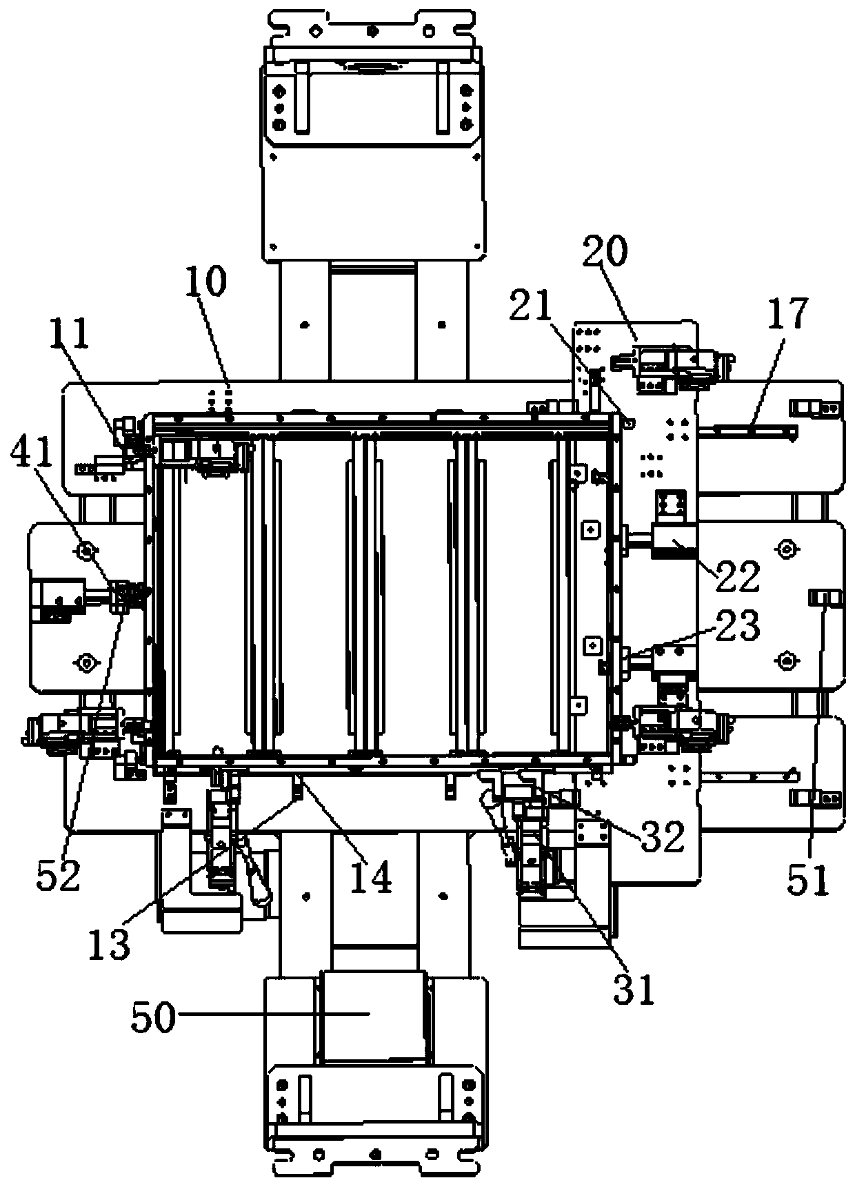
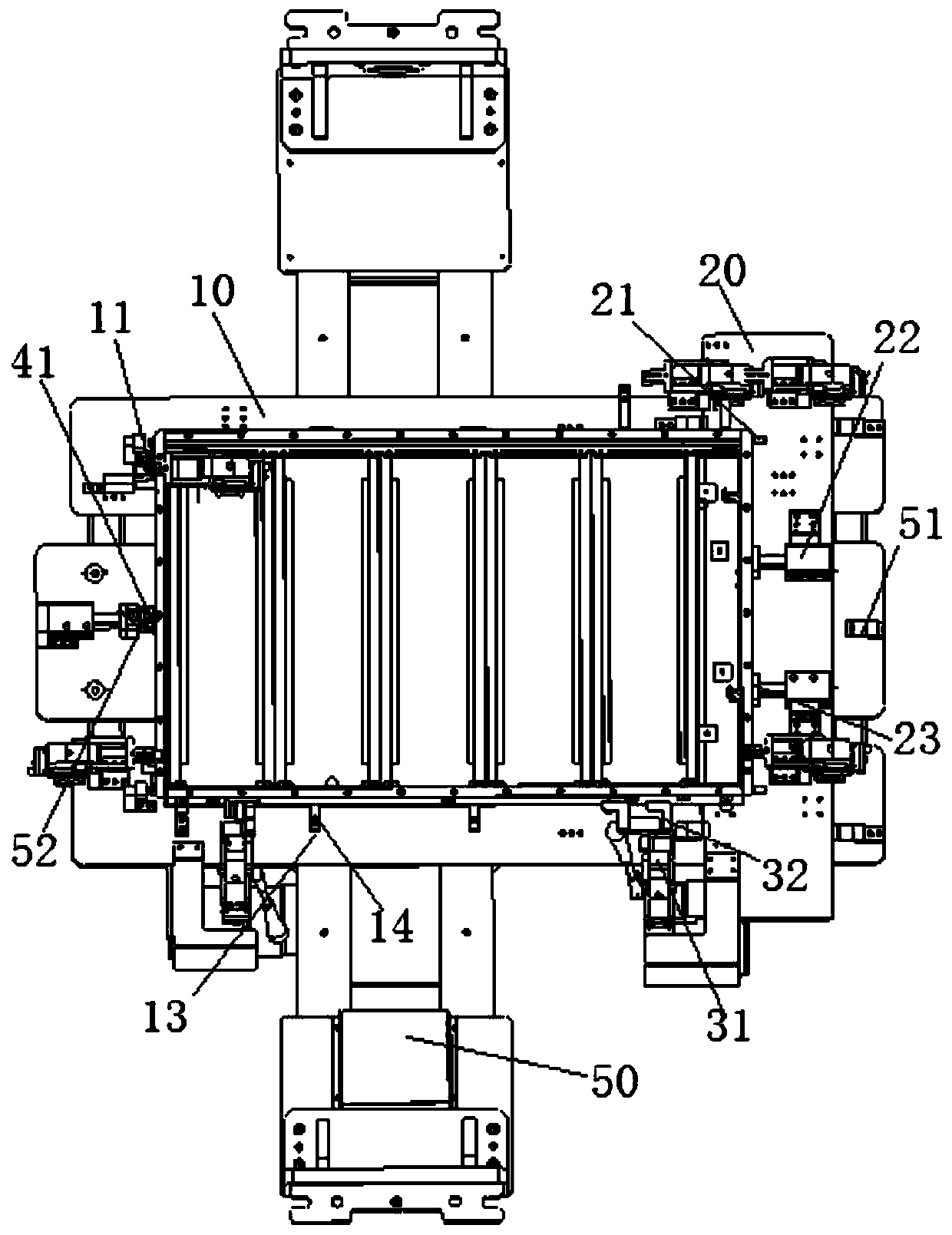
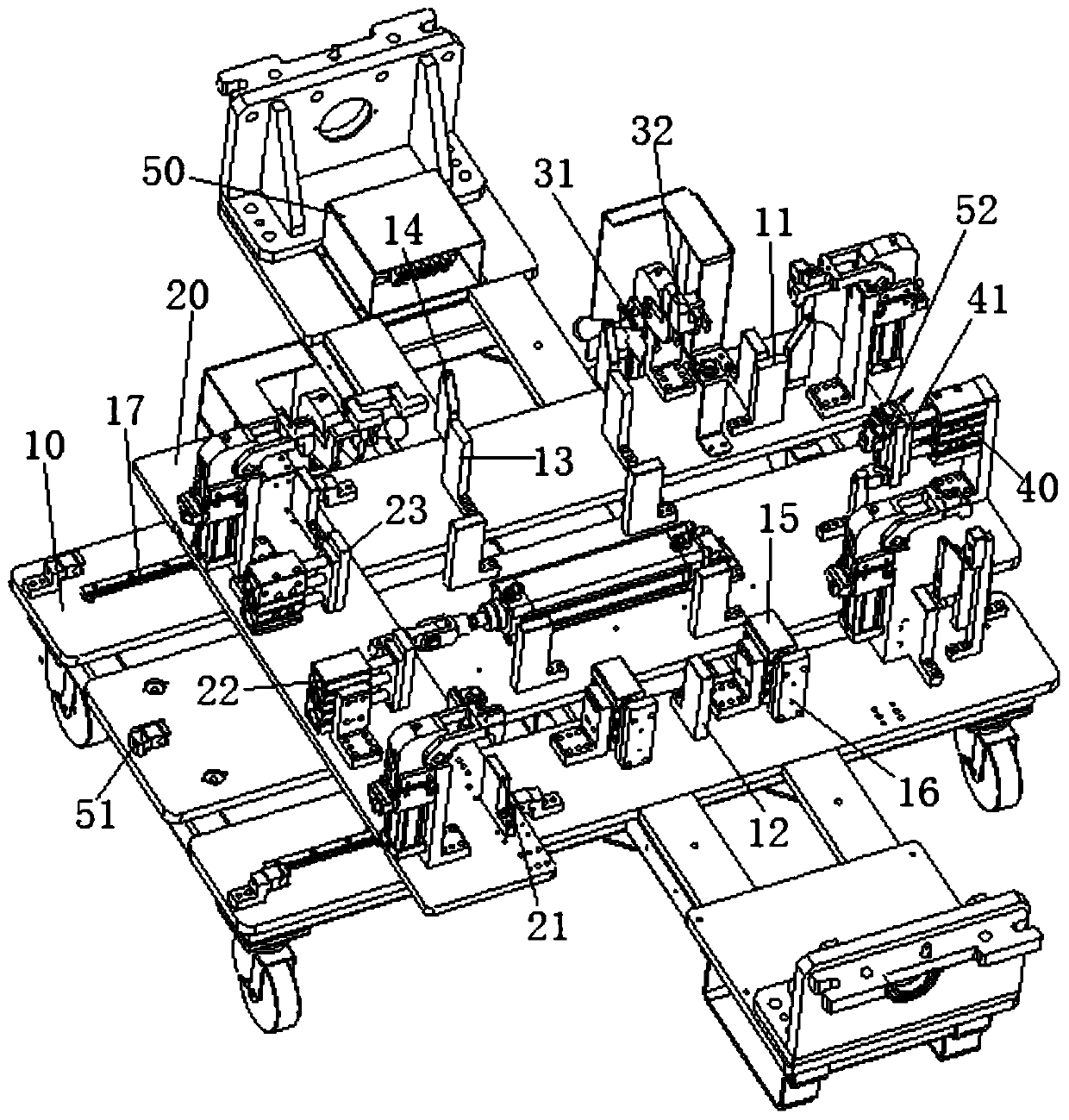
[0025] refer to Figure 1 to Figure 5 , Figure 1 to Figure 5 It is a structural schematic diagram of a specific embodiment of the present invention.

[0026] An automatic detection flexible welding fixture provided in this embodiment is mainly used for welding two or more battery trays with different lengths including lifting lugs, bushings and harness brackets, and the outer frames of different battery trays have the same shape and characteristics , The components such as lifting lugs, bushings and harness brackets on the battery tray are also shared, the difference is only in the length of the tray and the positions of the lifting lugs and bushing holes.

[0027] Such as Figure 1 to Figure 5 As shown, an automatic detection flexible welding fixture and its working method include a fixture base 10 and a welding robot controller 50, the fixture base 10 is provided with a switching slide rail 17, and the switching slide rail 17 is provided with a switching slide seat 20, t...


PUM


Abstract

The invention discloses an automatic detection flexible welding fixture, which includes a fixture base and a welding robot controller. A switching sliding rail is arranged on the fixture base, a switching sliding seat is arranged on the switching sliding rail, a first laser range finder for detecting the position of the switching sliding seat and a second laser range finder for detecting the position of a workpiece are arranged on the fixture base, the first laser range finder and the second laser range finder are arranged at the both ends of the length direction of the switching sliding railcorrespondingly, and the first laser range finder and the second laser range finder are both connected with the welding robot controller through signals. According to the automatic detection flexiblewelding fixture and a working method thereof, one welding fixture can be used for processing battery trays with various specifications and sizes in a welding mode, whether workpiece placement meets the set requirements or not can be automatically detected, and welding robot control programs corresponding to the workpiece length specifications are automatically selected.

Description

technical field [0001] The invention relates to the technical field of a welding operation auxiliary device, in particular to an automatic detection flexible welding fixture and a working method thereof. Background technique [0002] An electric vehicle (BEV) refers to a vehicle that is powered by a vehicle-mounted power supply, drives the wheels with a motor, and meets the requirements of road traffic and safety regulations. Due to its smaller impact on the environment than traditional cars, its prospects are widely optimistic. At present, a large number of companies and brands of electric passenger cars, electric buses, and electric trucks have emerged in China. The specifications and sizes of battery trays required by different companies and brands of electric vehicles are also different. [0003] The welding of components such as bushings and lifting lugs of battery trays of different specifications and sizes is also different, and battery trays have high requirements f...

Claims


Application Information

Patent Timeline
Patent Type & Authority Applications(China)
IPC IPC(8): B23K37/00B23K37/04
Inventor 李耀熙
Owner 珠海城市职业技术学院
Why Eureka
Try Eureka