A hydraulic intelligent control valve
A technology of intelligent control and pressure control, applied in the field of hydraulic control valves, to simplify hardware design, facilitate manufacturing costs, and reduce hardware types
- Summary
- Abstract
- Description
- Claims
- Application Information
AI Technical Summary
Problems solved by technology
Method used
Image
Examples
Embodiment 1
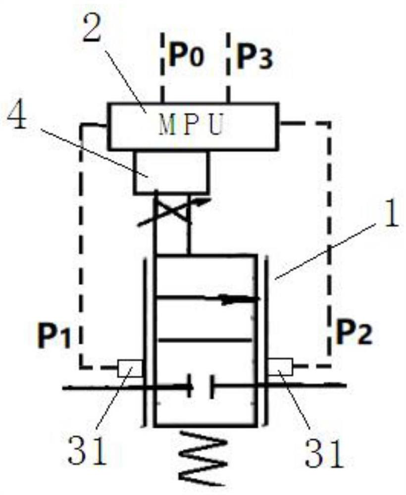
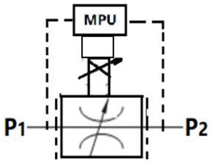
[0034]CombineFigure 1 to Figure 3As shown, in this embodiment, the electronically controlled main valve selects a high-speed switching proportional pilot valve, and the spool of the proportional pilot valve acts under the combined action of the proportional solenoid force and the spring force to achieve the valve port Adjust the size of the opening between closed and fully open.
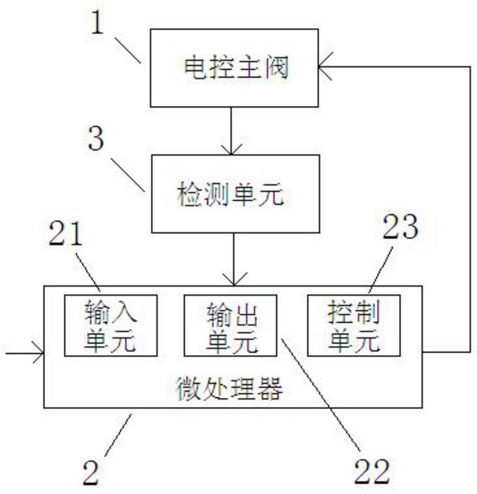
[0035]In this embodiment, the control signal is a valve opening control signal. The control unit of the microprocessor receives the valve port opening control signal, and directly controls the change of the valve port opening of the electronically controlled main valve accordingly, so as to complete the control of the liquid flow through the electronically controlled main valve according to the flow formula. The throttle valve control function of the electronically controlled main valve.
[0036]Among them, the flow formula corresponding to the hydraulic throttling element is:
[0037]
[0038]In the formula, Q(τ)—flo...
Embodiment 2
[0046]Combinefigure 1 withFigure 4 As shown, the electronically controlled main valve with the same structure as that of the first embodiment is adopted. The difference is that the control signal includes a valve port opening control signal and a pressure detection signal. The control unit of the microprocessor receives the valve port opening control signal and the pressure detection signal, and controls the valve port opening change of the electronically controlled main valve according to the relationship between the inlet pressure and the outlet pressure. Among them, when the inlet pressure P1Greater than outlet pressure P2When the valve port opening of the electronically controlled main valve changes according to the change of the valve port opening control signal, on the contrary, when the inlet pressure P1Less than or equal to outlet pressure P2At this time, the valve port opening of the electronic control main valve is at the maximum state, that is, the electronic control main...
Embodiment 3
[0049]Combinefigure 1 withFigure 5 As shown, the electronically controlled main valve with the same structure as that of the first embodiment is adopted. The difference is that the control signal includes the valve port opening control signal and the pressure detection signal. The control unit of the microprocessor receives the valve port opening control signal and the pressure detection signal, and controls the valve port opening change of the electronically controlled main valve according to the relationship between the inlet pressure and the outlet pressure. Among them, the valve port opening control signal and the inlet pressure P1And outlet pressure P2The pressure difference between is correlated, and the microprocessor is based on the inlet pressure P1And outlet pressure P2The pressure difference changes between the two, adjust the valve port opening control signal input to the electronic control main valve, so that the inlet pressure P1And outlet pressure P2The pressure diffe...
PUM
 Abstract
Description
Claims
Application Information
 - R&D
- Intellectual Property
- Life Sciences
- Materials
- Tech Scout
- Unparalleled Data Quality
- Higher Quality Content
- 60% Fewer Hallucinations
Browse by: Latest US Patents, China's latest patents, Technical Efficacy Thesaurus, Application Domain, Technology Topic, Popular Technical Reports.
© 2025 PatSnap. All rights reserved.Legal|Privacy policy|Modern Slavery Act Transparency Statement|Sitemap|About US| Contact US: help@patsnap.com


