Heat shield for stove and stove using heat shield for stove

A technology for heat shields and stoves, applied in the field of stoves, can solve the problems of sliding pans, overflowing of cooking soup, swinging of combustion flames of gas stoves, flameout of gas stoves, etc., achieving ingenious structure, protecting flames and preventing radiation. Effect

Pending Publication Date: 2019-06-11
NINGBO FOTILE KITCHEN WARE CO LTD
View PDF2 Cites 4 Cited by
  • Summary
  • Abstract
  • Description
  • Claims
  • Application Information

AI Technical Summary

Problems solved by technology

In the actual use of existing gas stoves, since the pot is placed on the pot support for heating, there is a certain space between the pot and the burner. A part escapes into the surrounding environment, causing energy waste; in order to solve the above problems, some heat collection and energy gathering have occurred in China in recent years, such as the "energy gathering ring for gas stoves and gas stoves with it" disclosed in Chinese patent CN203404823U ", and as disclosed in Chinese patent CN204042984U "a kind of energy-gathering gas cooker", the cooker also has an energy-gathering pan support, although the above-mentioned energy-gathering ring structure can reduce the consumption of heat energy to a certain extent, but Gas stoves are generally placed in the ventilated place of the kitchen. When the wind in the external environment is strong, the combustion flame of the gas stove may swing, become unstable, and sometimes even cause flameout, affecting use
In addition, existing ordinary gas stoves still have slippery pots, and cooking soup overflows into the burner burner, fire holes, etc., causing gas stoves to extinguish and fail to ignite.

Method used


Image

  • Heat shield for stove and stove using heat shield for stove
  • Heat shield for stove and stove using heat shield for stove
  • Heat shield for stove and stove using heat shield for stove

Examples


Embodiment 1

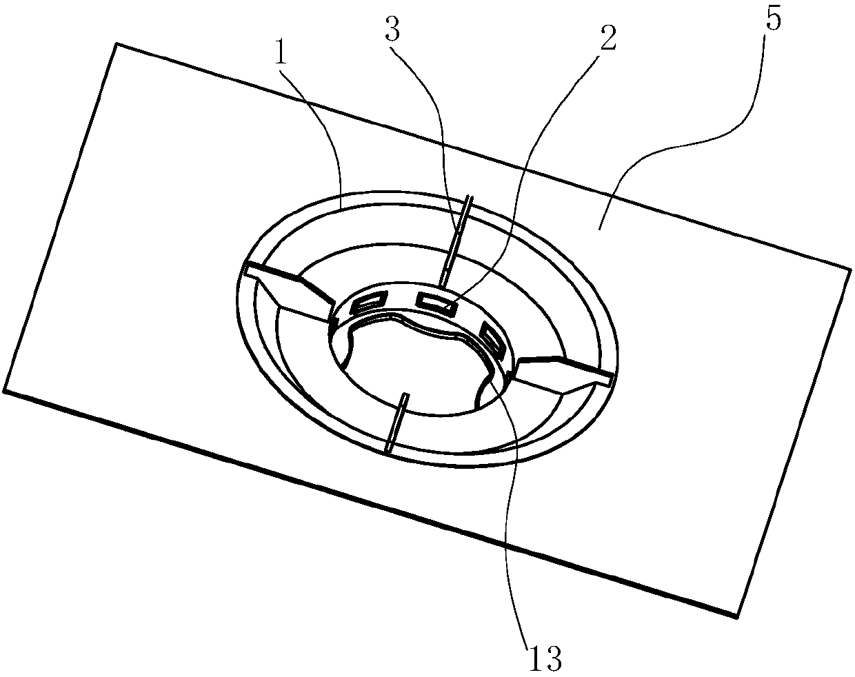
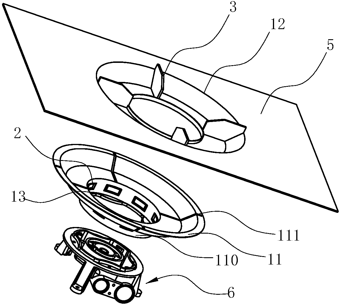
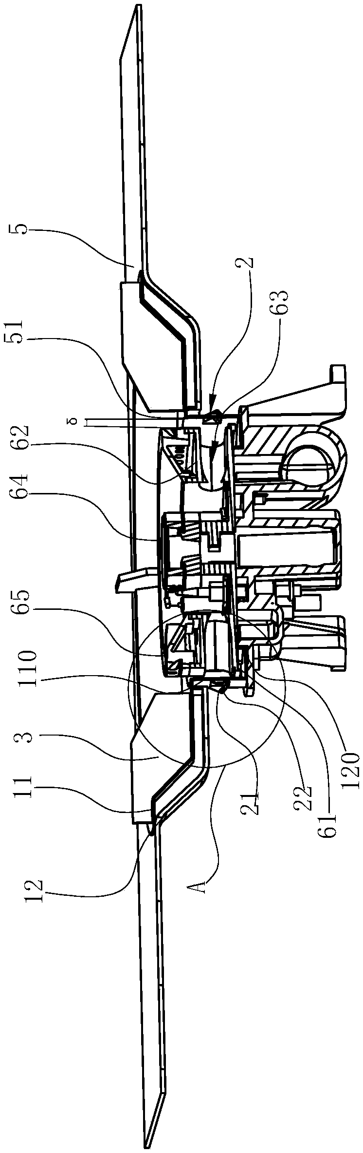
[0024] Such as Figure 1~4 As shown, the stove heat shield in this embodiment includes an annular cover body 1, the cover body 1 is a double-layer structure and has a cavity 4, the cavity 4 is filled with air, and the excellent thermal insulation properties of air are used to Reduce the heat transfer from the cover body 1 to the outside. The annular wall 110 of the central through hole of the cover body 1 protrudes downwards and has an upwardly protruding edge 120 extending horizontally to form a circle of an annular liquid collecting pan 13 for collecting spillage. In order to make the air outside the cover 1 flow into the area surrounded by the annular wall 110 of the cover 1 through the secondary air inlet hole 2, the annular wall 110 of the central through hole is provided with secondary air inlet holes 2 at intervals in the circumferential direction, wherein , in order to prevent the overflow from flowing out of the cover body 1, the secondary air inlet 2 is formed by pa...


PUM


Abstract

The invention relates to a heat shield for a stove. The heat shield comprises an annular shield body. The heat shield is characterized in that the bottom of the shield body is provided with an annularliquid collecting tray extending in the horizontal direction of a center hole. Compared with the prior art, the heat shield has the advantages that on the basis of an existing gas stove, the heat shield for the stove is additionally arranged, a ring of annular liquid collecting tray for collecting overflowing liquid is additionally arranged at the bottom of the heat shield, and liquid can be effectively prevented from overflowing and entering a burner. Meanwhile, the heat shield is internally and fixedly provided with pot landing legs, the contact area between the pot landing legs and a pot can be increased, and therefore a flame can fully exchange heat with the bottom of the pot, heat absorbed by the pot landing legs can heat the bottom of the pot as much as possible through heat conduction, and the heat loss of the flame is reduced. The invention also discloses the stove using the heat shield, the liquid collecting tray of the shield body is matched with a base of the burner, liquidon the heat shield can finally flow into the liquid collecting tray, the pot landing legs, the liquid collecting tray and the heat-insulating performance are integrated, and the structure is ingenious and reliable.

Description

technical field [0001] The invention relates to a heat shield for a cooker, and also relates to a cooker using the heat shield for a cooker. Background technique [0002] With the development of the city gas industry, my country's stove industry has greatly improved in terms of variety, material, performance, and sales. A very important point in its performance improvement is the improvement of thermal efficiency. The burners of household gas stoves are mostly atmospheric burners. The atmospheric burner is a burner designed according to the partial premixing method, and its primary air coefficient is 0<α<1. The atmospheric burner is divided into two parts: the head and the ejector. The ejector is used to eject the primary air required for combustion, and the function of the burner head is to evenly distribute the mixture of gas and air to the fire hole for stable and complete combustion. The gas of the gas stove is mainly liquefied petroleum gas, natural gas, bioga...

Claims


Application Information

Patent Timeline
Patent Type & Authority Applications(China)
IPC IPC(8): F24C15/10F24C15/34F24C3/00F24C15/14
Inventor 吴丽波邵海忠郑军妹茅忠群诸永定
Owner NINGBO FOTILE KITCHEN WARE CO LTD
Why Eureka
Try Eureka