Floor radiation air conditioner system, air conditioner floor assembly, heat preservation module and pavement method

A thermal insulation module and floor technology, which is applied in the field of floor radiant air-conditioning systems and air-conditioning floor components, and thermal insulation modules, which can solve the problems that the good use status of the floor heating system cannot be effectively ensured, it is difficult to find the correct leak point, and the operation convenience is low, etc. problems, to achieve the effect of reducing the ineffective loss of heat, improving the efficiency of laying operations, and improving the efficiency of heat dissipation

Inactive Publication Date: 2019-06-11
BEIJING BOTIANZIRUI TECH CO LTD
View PDF4 Cites 1 Cited by
  • Summary
  • Abstract
  • Description
  • Claims
  • Application Information

AI Technical Summary

Problems solved by technology

Due to the limitations of concrete construction and buried pipelines, it is not easy to find the correct leaking point in the event of a leaking fault. Even if the leaking point is found, it is easy to repair, and the construction cost is also high
In addition, the laying method of the existing floor hea

Method used


Image

  • Floor radiation air conditioner system, air conditioner floor assembly, heat preservation module and pavement method
  • Floor radiation air conditioner system, air conditioner floor assembly, heat preservation module and pavement method
  • Floor radiation air conditioner system, air conditioner floor assembly, heat preservation module and pavement method

Examples


Embodiment 1

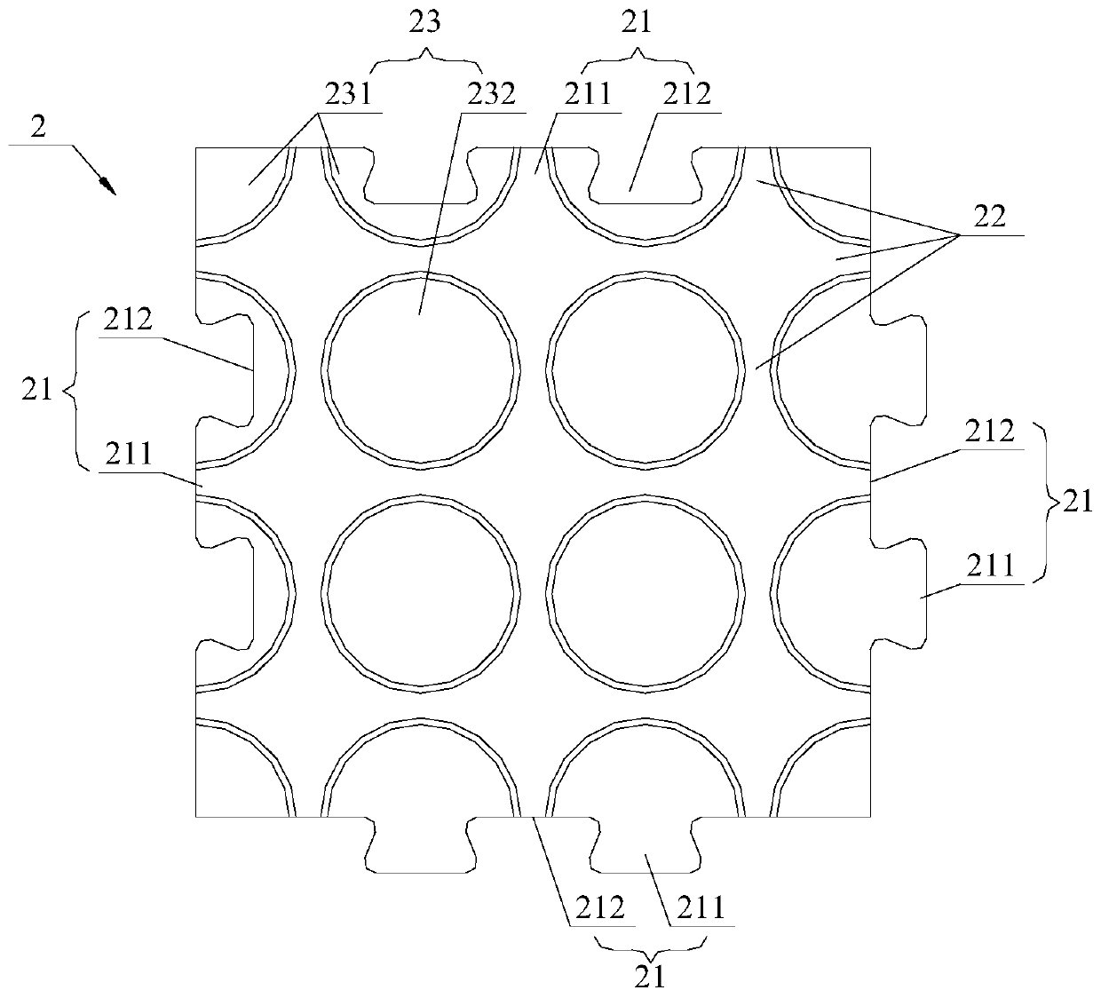
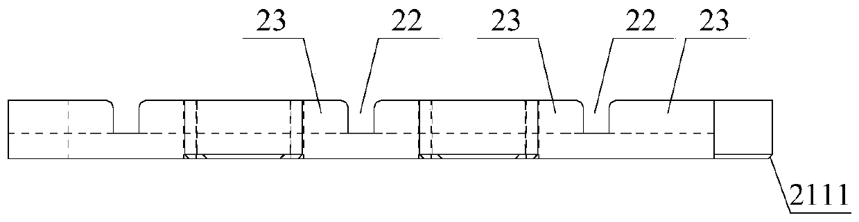
[0054] Please also see Figure 2-4 ,in, figure 2 is the front view of the insulation module, Figure 4 is the bottom view of the insulation module, Figure 5 It is the rear view of the insulation module.

[0055] In this solution, the outer periphery of the thermal insulation module 2 is provided with an assembly interface portion 21, so that the adjacent thermal insulation modules 2 can be assembled sequentially according to the laying space; here, the assembly interface portion 21 includes an outer convex insertion structure 211 and an inner concave accommodation structure. 212, the shape and size of the two are consistent, so that they can be assembled.

[0056] As shown in the figure, the protruding insertion structure 211 on one side of the thermal insulation module 2 is matched with the concave accommodation structure 212 on the opposite side. The accommodating structure 212 and the protruding insertion structure 211 are fitted together, so that they can be arranged...

Embodiment 2

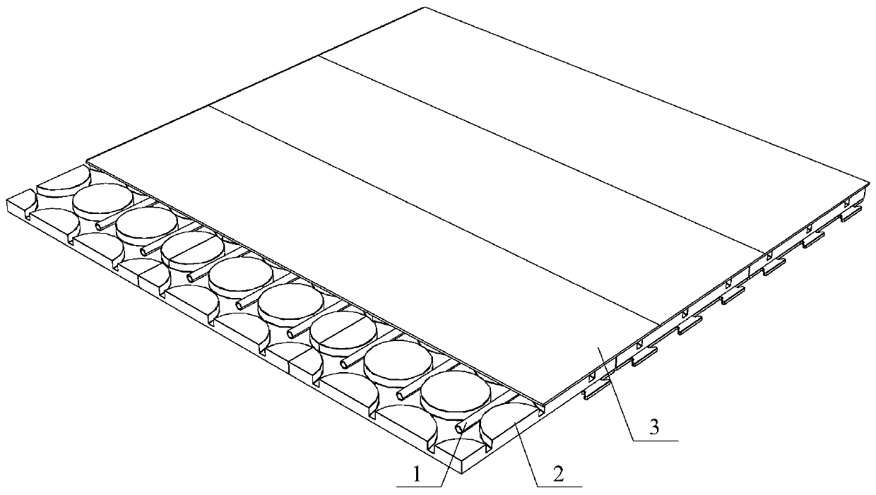
[0069] See Figure 7 and Figure 8 ,in, Figure 7 A schematic diagram of the air-conditioning floor assembly described in Embodiment 2 is shown, Figure 8 for Figure 7 A schematic diagram of the typical assembly relationship of the thermal insulation module shown in .

[0070] The core idea of ​​this embodiment is the same as that of Embodiment 1. The difference is that the heat preservation module 2 provided by this solution is not provided with an assembly interface. mark to indicate.

[0071] combine Figure 8 As shown, the heat preservation module 2 is provided with pipe slots 22, and is configured as follows: after the heat preservation modules 2 are assembled sequentially according to the laying space, the pipe slots 22 on the adjacent heat preservation modules 2 can be connected to form the heat pipe installation path of the air-conditioning floor assembly; And after the assembly is completed, the gap between adjacent insulation modules 2 is 0.05 mm to 0.3 mm, wh...


PUM

PropertyMeasurementUnit
Thermal conductivityaaaaaaaaaa
Densityaaaaaaaaaa
Gapaaaaaaaaaa

Abstract

The invention discloses a floor radiation air conditioner system, an air conditioner floor assembly, a heat preservation module and a pavement method. Splicing connector parts are arranged on the periphery of the heat preservation module, and heat preservation modules are sequentially spliced according to the pavement space; pipe inserting grooves are formed in the upper surface of the heat preservation module, according to the arrangement, after the heat preservation modules are sequentially spliced according to the pavement space, the pipe inserting grooves in the adjacent heat preservationmodules can be in communication, and a heat pipe installing passageway of the air conditioner floor assembly is formed. Through structure optimization, the pavement operation efficiency and maintenance convenience can be effectively improved, good silencing and sound isolating functions are combined, and the technology guarantee is provided for obtaining the ideal heat exchange efficiency on the basis of integral client experience improving.

Description

technical field [0001] The invention relates to the technical field of geothermal flooring, in particular to a floor radiant air-conditioning system, an air-conditioning floor assembly, a thermal insulation module, and a paving method. Background technique [0002] As we all know, compared with radiator heating, floor radiant heating is widely used because of its characteristics in line with the development of building energy-saving technology. Specifically, the heat medium in the floor is used to evenly heat the entire floor, and the law of ground radiation is used to conduct from bottom to top to achieve the purpose of heating. [0003] The existing floor heating system using hot water is mainly to bury metal or synthetic resin pipes underground, and heat the water through a boiler installed indoors or outdoors to generate heat to establish a heat medium circulation. Due to the limitations of concrete construction and buried pipelines, it is not easy to find the correct l...

Claims


Application Information

Patent Timeline
IPC IPC(8): F24F5/00E04F15/10E04F15/22
Inventor 赵峰
Owner BEIJING BOTIANZIRUI TECH CO LTD
Why Eureka
Try Eureka