A skull decompression connector
A technology of connectors, skulls, applied in the field of medical devices
- Summary
- Abstract
- Description
- Claims
- Application Information
AI Technical Summary
Problems solved by technology
Method used
Image
Examples
Embodiment 1
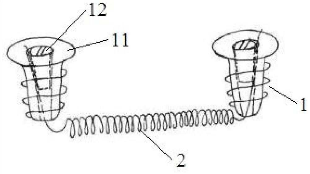
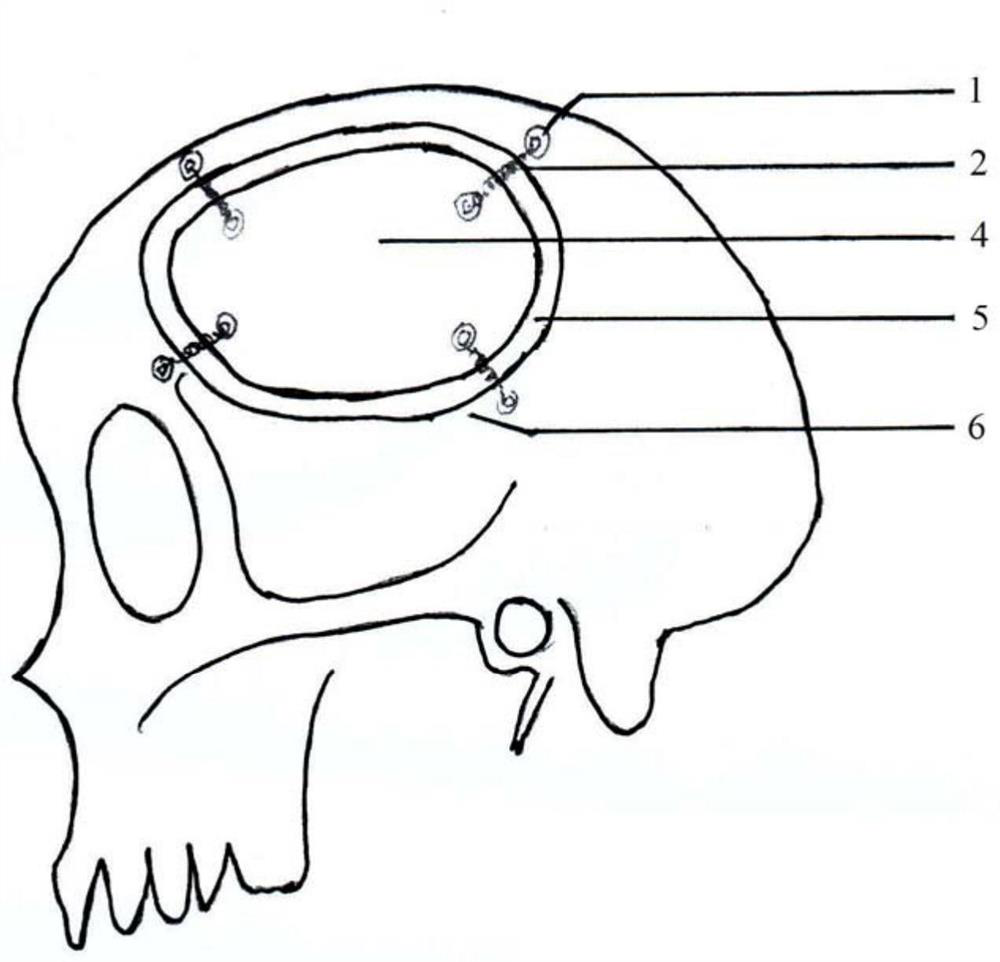
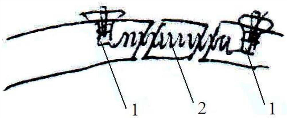
[0032] The structure of Embodiment 1 of the present invention is as follows Figure 1 to Figure 4 As shown, the skull decompression connector in this embodiment includes two screws 1 and an elastic connector 2 connected between the two screws 1. The elastic connector 2 in this embodiment is a spring, and the spring is made of stainless steel wire or titanium The two ends of the elastic connector 2 are respectively connected with two screws 1, one screw is used for fixed connection on the bone window, and the other screw is used for fixed connection on the bone plate. The screw 1 includes a hollow external screw 11 and an external screw 12 with external threads. The hollow part of the external screw 11 has internal threads, and the internal screw 12 is threadedly connected to the hollow part of the external screw 11. The elastic connector 2 The end of the outer screw passes through the hollow part of the outer screw and is clamped between the inner screw 12 and the outer screw ...
Embodiment 2
[0040] The difference from Embodiment 1 of the present invention is that the connection method between the screw and the elastic connecting piece is different in this embodiment, and the connecting piece is used to connect the screw and the elastic connecting piece in this embodiment. The structure of the second embodiment of the present invention is as follows Figure 5 to Figure 6 As shown, the skull decompression connector of this embodiment further includes two connecting pieces 3, and each connecting piece 3 is provided with a screw through hole 31 and a connecting piece through hole 32, and the screw 1 is threaded on the screw through hole 31, The elastic connecting piece 2 is fixed on the connecting piece through hole 32, and the screw 1 is a cancellous bone screw. The rest of this embodiment is the same as that of Embodiment 1, and details are not repeated here.
[0041] When the patient undergoes craniotomy, the cut skull plate does not need to be discarded. The two ...
Embodiment 3
[0043] The difference from Embodiment 1 of the present invention is that the connection between the screw and the elastic connector in this embodiment is different. The structure of Embodiment 3 of the present invention is as follows: Figure 7 As shown, in this embodiment, two ends of the elastic connecting member 2, ie, the spring, are respectively wrapped around two screws 1, and the screws 1 are cancellous screws. The rest of this embodiment is the same as that of Embodiment 1, and details are not repeated here.
[0044] When the patient undergoes craniotomy, the cut skull plate does not need to be discarded. The two ends of the elastic connection are wrapped around two screws respectively, and then the two outer screws are fixed on the bone window and the bone plate respectively, so that the The bone window and the bone plate are connected together.
[0045] In other embodiments of the present invention, the two ends of the elastic connecting piece 2 can also be provided...
PUM
 Abstract
Description
Claims
Application Information
 - R&D
- Intellectual Property
- Life Sciences
- Materials
- Tech Scout
- Unparalleled Data Quality
- Higher Quality Content
- 60% Fewer Hallucinations
Browse by: Latest US Patents, China's latest patents, Technical Efficacy Thesaurus, Application Domain, Technology Topic, Popular Technical Reports.
© 2025 PatSnap. All rights reserved.Legal|Privacy policy|Modern Slavery Act Transparency Statement|Sitemap|About US| Contact US: help@patsnap.com


