Planer type milling machine with hot knife line milling and scraping spiral scrap iron anti-splash device

A gantry milling machine, anti-splash technology, applied in the field of milling machines, can solve the problems of scratching the work surface, scrapping material blocks, affecting the stability of iron block placement, etc.

Active Publication Date: 2019-06-14
嵊州市法克机械有限公司
View PDF7 Cites 2 Cited by
  • Summary
  • Abstract
  • Description
  • Claims
  • Application Information

AI Technical Summary

Problems solved by technology

[0004] Aiming at the deficiencies in the prior art, the object of the present invention is to provide a gantry milling machine with a device for milling and scraping spiral iron filings with hot knife patterns, so as to solve the problem of frictional heating between two hard blocks due to the pressurized cutting of iron blocks by the milling cutter. Deformation is necessary to cut off the corners of the iron block softened by heating to achieve the effect of milling machine processing workpieces. However, thermal deformation will also cause the iron wire after cutting at the knife edge to wrap around the knife grain surface during rotary cutting, causing centrifugal force to spirally fly out iron chips However, iron filings that lose thermal friction will splatter, and the texture will harden after cooling, which will cause scratches on the work surface, affect the stability of the iron block in the later stage, and cause the next iron block to tilt horizontally when cutting, thus scrapping the material block A waste of cost, splashing too far will also hurt the staff and cause safety hazards, and the problem of insufficient protection for spiral wire strips of iron filings

Method used


Image

  • Planer type milling machine with hot knife line milling and scraping spiral scrap iron anti-splash device
  • Planer type milling machine with hot knife line milling and scraping spiral scrap iron anti-splash device
  • Planer type milling machine with hot knife line milling and scraping spiral scrap iron anti-splash device

Examples


Embodiment Construction

[0030] In order to make the technical means, creative features, goals and effects achieved by the present invention easy to understand, the present invention will be further described below in conjunction with specific embodiments.

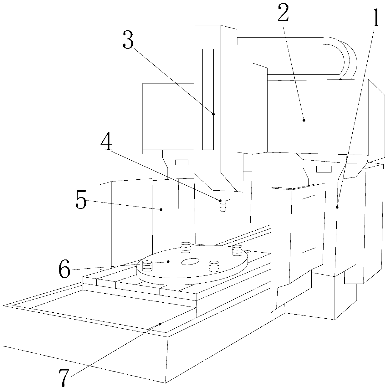
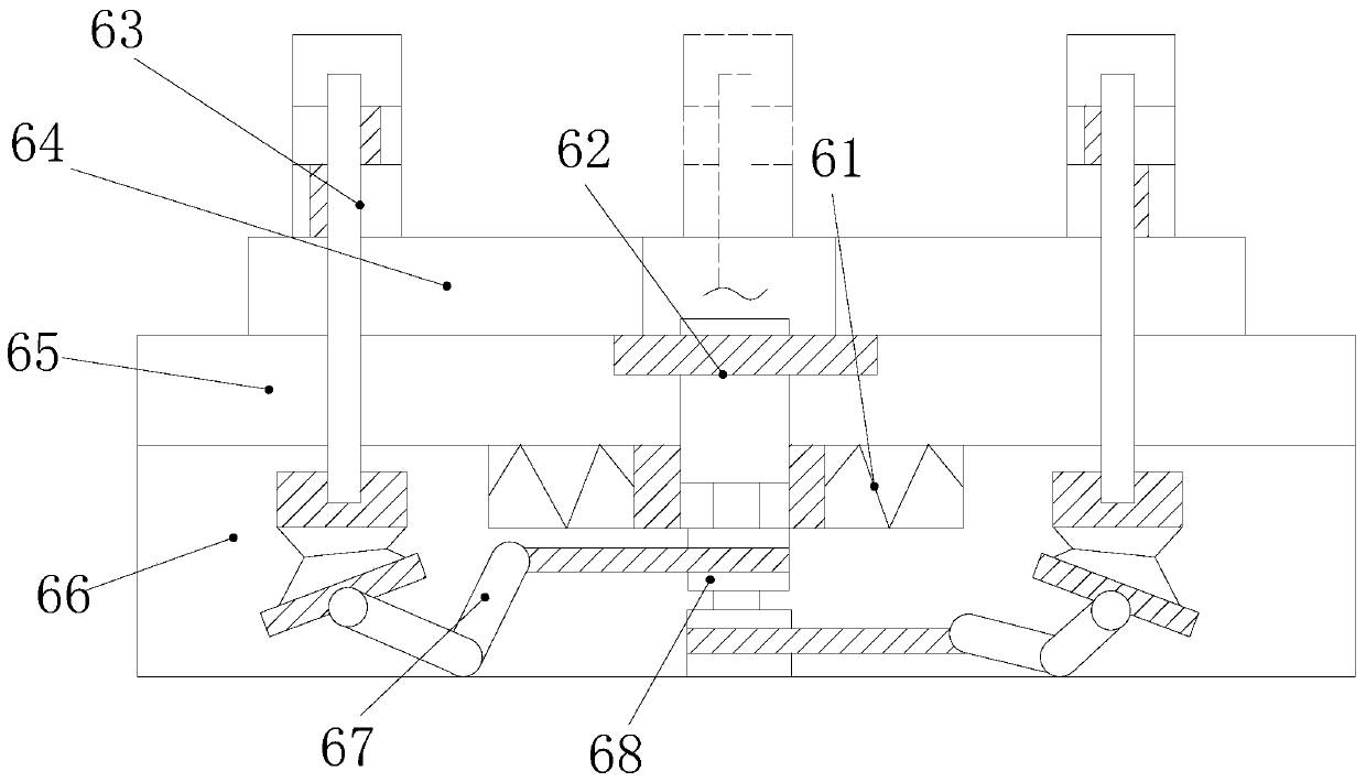
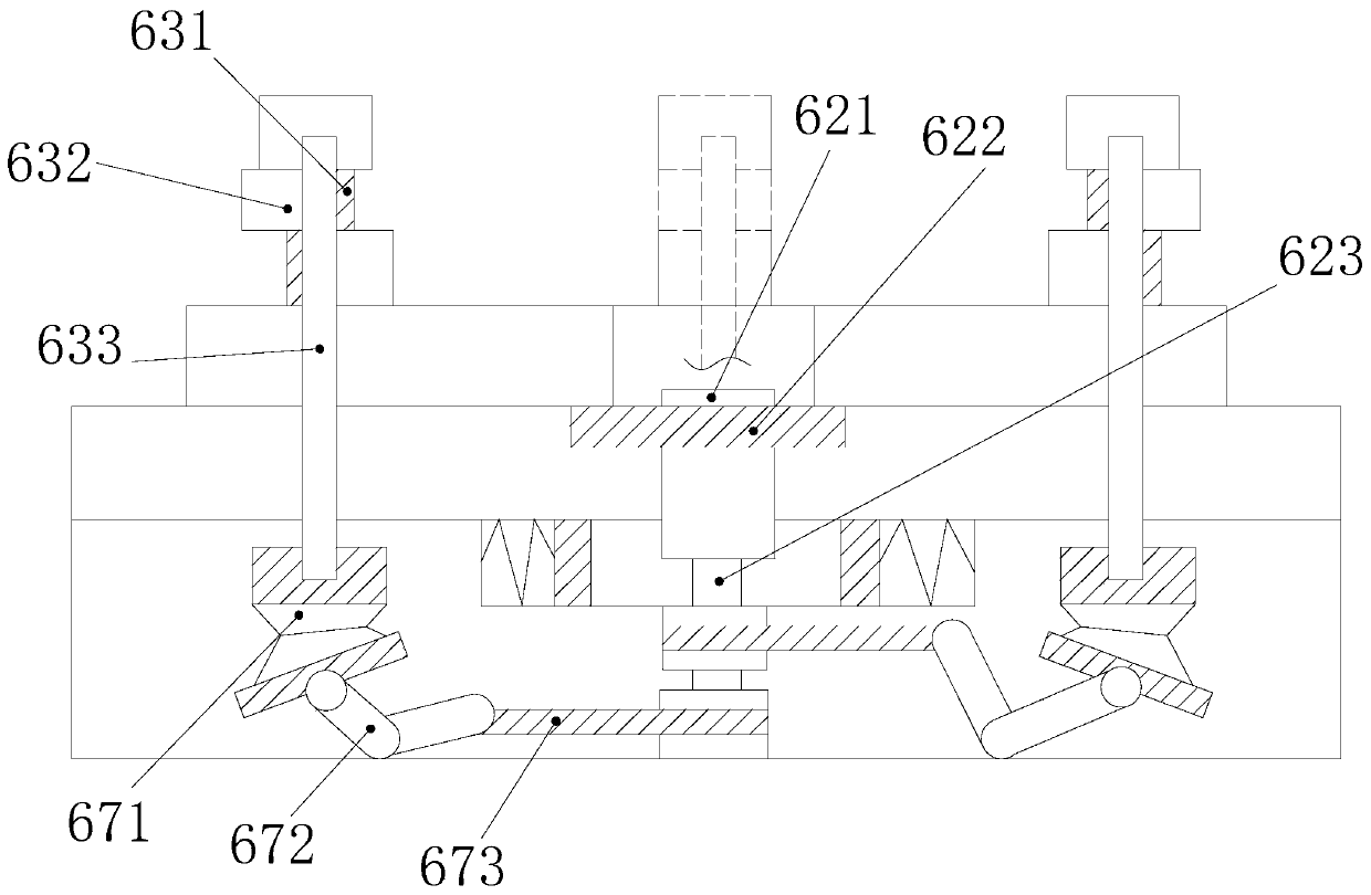
[0031] see Figure 1-Figure 7, the present invention provides a gantry milling machine with a hot knife pattern milling and scraping spiral iron chip anti-splash device, its structure includes: supporting column 1, gantry beam block 2, motor front end cover 3, milling cutter convex rod 4, observation baffle 5 , spacer alloy disc seat 6, base 7, the bottom end of the milling cutter convex rod 4 is movably connected with the top surface of the spacer alloy disc seat 6, and the spacer alloy disc seat 6 is inserted into the base 7 In the middle part, the top end of the milling cutter protruding rod 4 is inserted and embedded under the bottom of the motor front end cover 3, the motor front end cover 3 is mechanically connected with the gantry beam bloc...


PUM


Abstract

The invention discloses a planer type milling machine with a hot knife line milling and scraping spiral scrap iron anti-splash device. The planer type milling machine structurally comprises a supporting column, a gantry beam block, a motor front end cover, a milling cutter protruding rod, an observation baffle, a separating mat alloy disc seat and a base. The milling cutter protruding rod is matched with the separating mat alloy disc seat; according to the magnetic attraction of iron, a separating mat disc is arranged on a working table plate, alloy metal molecular keys are tightly compressed,the hardness is high, and scrapping is prevented; magnet misalignment columns are inserted at four orientations of a main shaft column in an opposite-angle manner, hemispherical wrapping of a spiralmagnetic field is formed, and therefore scrap iron strips cut by a cutter on a milling machine can fly out to be attracted to the magnet misalignment columns; the whole separating mat disc is in rotary fit with the magnet misalignment columns to rotate, the compass effect of roller composition motion is formed, angle fine adjustment is used on a coordinate system to improve the machining accuracyof a workpiece, a worker can take out the magnet misalignment columns to remove the scrap iron strips in the later period, magnetic field control is formed within the scrap iron splashing scope, and the overall equipment performance is improved.

Description

technical field [0001] The invention relates to a gantry milling machine with an anti-splash device for milling and scraping spiral iron filings with hot knife lines, belonging to the field of milling machines. Background technique [0002] The gantry milling machine is an important equipment for processing large steel blocks into building profiles or mold shell frames. There are a variety of knife patterns for different depths of cutting in the tool magazine for milling cutters. It is one of the advanced equipment for high-precision machining. The processing of steel workpieces is also very meticulous and efficient. The shortcomings of the current technology that need to be optimized are: [0003] Since the milling cutter is pressurized to cut the iron block, frictional heating and thermal deformation between the two hard blocks is necessary, so as to cut off the corners of the iron block that are softened by the temperature rise, so as to achieve the effect of milling mach...

Claims


Application Information

Patent Timeline
Patent Type & Authority Applications(China)
IPC IPC(8): B23C1/06B23C9/00B23Q11/00
Inventor 褚晓婷黄连福江利扬谢跃连
Owner 嵊州市法克机械有限公司
Why Eureka
Try Eureka