Welding gun control method and control system thereof

A control method and control system technology, applied in the direction of manufacturing tools, welding equipment, welding accessories, etc., can solve the problems of unsightly welding seam formation of workpieces, high requirements for welding operators, crashed welding torches, etc., to reduce requirements and labor intensity. , The effect of improving the degree of welding automation and saving production costs

Inactive Publication Date: 2019-06-14
HUAHENG WELDING +2
View PDF10 Cites 0 Cited by
  • Summary
  • Abstract
  • Description
  • Claims
  • Application Information

AI Technical Summary

Problems solved by technology

[0002] In the automatic welding work, especially when performing circular seam welding, due to the possible existence of problems such as low teaming accuracy and low processing accuracy of the welded workpieces, the walking trajectory of the welding torch in the high and low direction during the welding process may not be consistent with the The workpiece to be welded is completely fitted, and the welding torch is prone to fall, which may lead to unsightly weld seams of the workpiece, or lead to serious waste of cost such as product scrapping and damage to the welding torch
[0003] In the prior art, before automatic welding, the welding operator needs to manually inspect the welded workpieces. When the gap between the workpieces is found to be too large, it needs to be manually spot welded; and, during the automatic welding process, if When encountering equipment failure or inappropriate process parameters that may cause the workpiece to be welded through, it is often necessary for the welding operator to pay attention to the changes in the direction of the welding torch and the workpiece in time with the naked eye, adjust the arc length of the carriage in time, and stop the operation of the equipment through an emergency Or turn off the automatic tracking function in time to prevent the welding gun from falling due to the excessive gap between the workpiece or being burned through, which is time-consuming and laborious, and has high requirements for welding operators, which is not conducive to automated industrial production work

Method used


Image

  • Welding gun control method and control system thereof
  • Welding gun control method and control system thereof
  • Welding gun control method and control system thereof

Examples


Embodiment Construction

[0040] In order to enable those skilled in the art to better understand the technical solutions in the present invention, the technical solutions in the embodiments of the present invention will be clearly and completely described below in conjunction with the drawings in the embodiments of the present invention. Obviously, the described The embodiments are only some of the embodiments of the present invention, not all of them. Based on the embodiments of the present invention, all other embodiments obtained by persons of ordinary skill in the art without making creative efforts shall fall within the protection scope of the present invention.

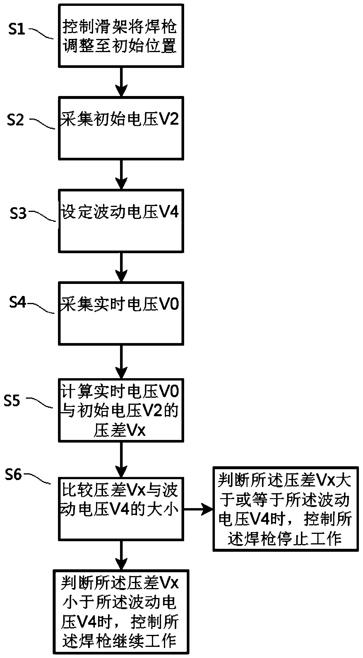
[0041] The present invention proposes a welding torch control method. In the present invention, the welding torch is controlled by a carriage to perform tracking welding. Specifically, the carriage can drive the welding torch to move in a vertical direction perpendicular to the welding seam. Generally, a stepping motor Driven to achieve...


PUM


Abstract

The invention provides a welding gun control method and a control system thereof. A welding gun is controlled by a sliding frame to carry out tracking welding. The control method comprises the following steps of controlling the sliding frame to adjust the welding gun to an initial position; turning on a power supply, collecting and recording the initial voltage V2 of electric arcs generated when the welding gun is located at the initial position; setting the fluctuation voltage V4; starting welding, tracking and collecting the real-time voltage V0 of electric arcs generated by the welding gunaccording to the real-time height of the welding gun in operation; calculating the voltage difference VX between the real-time voltage V0 and the initial voltage V2; when it is judged that the voltagedifference VX is smaller than the fluctuation voltage V4, controlling the welding gun to continue working; and controlling the welding gun to stop working when it is judged that the voltage difference VX is greater than or equal to the fluctuation voltage V4. The welding gun control method greatly reduces the degree of human intervention caused by burning through of workpieces in the welding process, improves the welding automation degree, improves the working efficiency, avoids the danger of welding gun falling, saves the production cost, and is more economical and efficient.

Description

technical field [0001] The invention belongs to the field of industrial automation, and in particular relates to a welding torch control method. Background technique [0002] In the automatic welding work, especially when performing circular seam welding, due to the possible existence of problems such as low teaming accuracy and low processing accuracy of the welded workpieces, the walking trajectory of the welding torch in the high and low direction during the welding process may not be consistent with the The workpiece to be welded is completely fitted, and the welding torch is prone to fall, which may lead to unsightly weld seams of the workpiece, or lead to serious waste of cost such as product scrapping and damage to the welding torch. [0003] In the prior art, before automatic welding, the welding operator needs to manually inspect the welded workpieces. When the gap between the workpieces is found to be too large, it needs to be manually spot welded; and, during the ...

Claims


Application Information

Patent Timeline
IPC IPC(8): B23K9/127B23K9/32
Inventor 吴晶晶
Owner HUAHENG WELDING
Why Eureka
Try Eureka