Method adopting continuous variable light spots for scanning processing in 3D printing

A 3D printing and laser scanning technology, applied in the field of 3D printing, can solve problems such as over-curing, affecting product surface quality, and reducing scanning efficiency, so as to improve quality, improve molding success rate, and improve scanning efficiency.

Active Publication Date: 2019-06-14
HUAZHONG UNIV OF SCI & TECH
View PDF4 Cites 6 Cited by
  • Summary
  • Abstract
  • Description
  • Claims
  • Application Information

AI Technical Summary

Problems solved by technology

Most of the unfilled areas obtained by Boolean operations belong to narrow and long areas with convex corners. When using a small spot for parallel scanning and filling, there will be a large number of turning and empty jumps, which reduces the scanning efficiency, and scanning this narrow area is prone to localization. The temperature is too high to cause over-curing, which affects the surface quality of the product

Method used


Image

  • Method adopting continuous variable light spots for scanning processing in 3D printing
  • Method adopting continuous variable light spots for scanning processing in 3D printing
  • Method adopting continuous variable light spots for scanning processing in 3D printing

Examples


Embodiment Construction

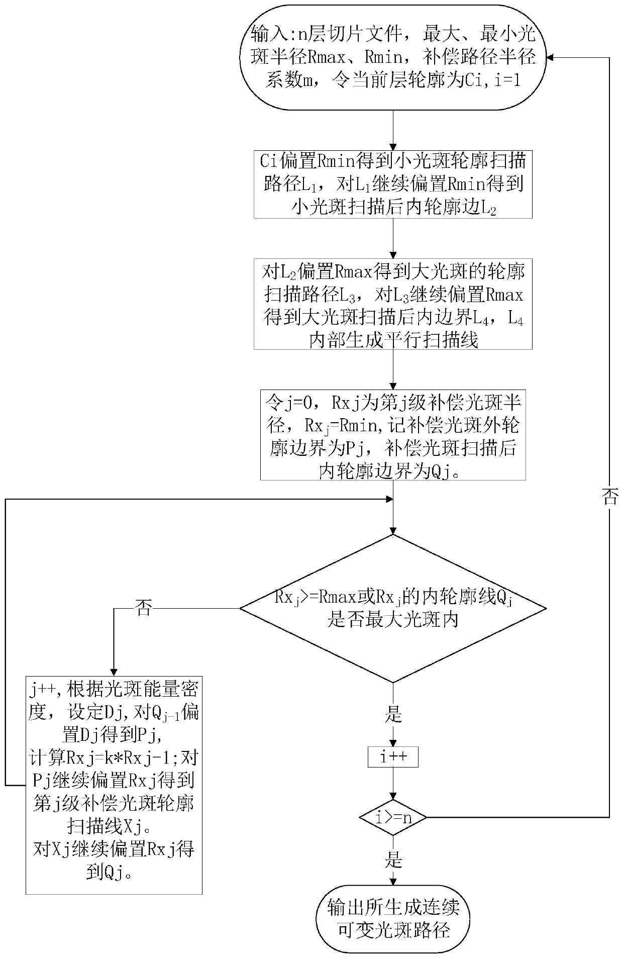
[0029] In order to make the object, technical solution and advantages of the present invention clearer, the present invention will be further described in detail below in conjunction with the accompanying drawings and embodiments. It should be understood that the specific embodiments described here are only used to explain the present invention, not to limit the present invention. In addition, the technical features involved in the various embodiments of the present invention described below can be combined with each other as long as they do not constitute a conflict with each other.

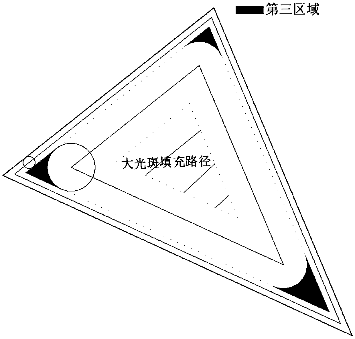
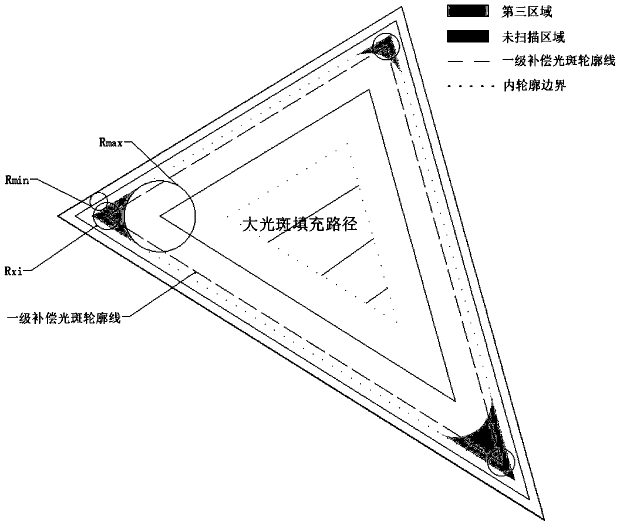
[0030] The existing photocuring rapid prototyping method with variable spot can use a larger spot for scanning and filling in the filling area by changing the size of the spot. Compared with the traditional fixed spot rapid prototyping method, it reduces the number of scanning and filling times and improves the molding efficiency. However, When using a large spot for contour scanning, there will...


PUM


Abstract

The invention belongs to the field of 3D printing, and particularly relates to a method adopting continuous variable light spots for scanning processing in 3D printing. The method comprises the following steps that for a single slicing layer in 3D printing, the maximum light spot radius and the minimum light spot radius of laser scanning processing are set, a to-be-scanned region is divided into afirst region, a second region and a third region, the first region is scanned and processed by adopting the minimum light spot, the second region is scanned and processed by adopting the maximum light spot, the third region adopts step-by-step compensation, namely the third region is scanned step by step by increasing the scanning radii of the light spots step by step, scanning processing of theregion is realized, and continuous variable light spot scanning processing is realized through continuous changing of the light spots in a way that the radii of the light spots are gradually increasedor reduced in the scanning process of the regions. According to the method, the scanning filling frequency is reduced, the forming efficiency is improved, and the local overheating curing of productsis avoided.

Description

technical field [0001] The invention belongs to the field of 3D printing, and more specifically relates to a method for scanning and processing with continuously variable light spots in 3D printing. Background technique [0002] 3D printing technology is an advanced manufacturing technology that has emerged in recent years. At present, 3D printing technologies mainly include photocuring, selective laser sintering, and fused deposition methods. The principle of photocuring 3D printing technology is that the computer controls the laser to emit a specific intensity. The laser scans the surface of the liquid photosensitive resin with a certain path, and the thin layer of resin in the scanned area undergoes photopolymerization and solidifies to form a thin layer of the printed part. Then a new layer of liquid resin is laid, and the next layer is scanned, and so on, until the entire print is completed. [0003] In the process of light-curing 3D printing, molding efficiency and su...

Claims


Application Information

Patent Timeline
Patent Type & Authority Applications(China)
IPC IPC(8): B29C64/129B29C64/393B33Y10/00B33Y50/02
Inventor 张李超李子健王森林胡汉伟赵祖烨史玉升
Owner HUAZHONG UNIV OF SCI & TECH
Why Eureka
Try Eureka