An ultra-low specific speed centrifugal pump device

A technology of specific speed and centrifugal pumps, which is applied in the direction of pump devices, components of pumping devices for elastic fluids, jet propulsion devices, etc., and can solve the problem of uneven circumferential velocity components at the front edge of the induction wheel and centrifugal wheel inlet, and unfavorable rockets. The stability of the engine system, the head and efficiency drop in small flow areas, etc., achieve the effects of light weight, reduced manufacturing process difficulty, and small structural size

Active Publication Date: 2020-11-06
XIAN AEROSPACE PROPULSION INST
View PDF6 Cites 0 Cited by
  • Summary
  • Abstract
  • Description
  • Claims
  • Application Information

AI Technical Summary

Problems solved by technology

[0004] 1) When designing a small flow pump, in order to obtain higher efficiency, it adopts the design of positive attack angle and increased flow rate, so that the liquid flow angle of the actual operating condition of the pump is smaller than the design liquid flow angle, so that the inducer and The front edge of the inlet of the centrifugal wheel has a non-uniform peripheral velocity component, resulting in a vortex around the flow, resulting in a decrease in lift and efficiency in the small flow area;
[0005] 2) The wake-jet flow of the centrifugal wheel and the volute, the separation of the secondary flow and the flow, and the stratification effect make the small flow area unstable
[0006] Patent No. ZL201010221455.8 discloses a low specific speed partial flow pump. Its impeller is a fully open structure. Usually, its highest efficiency point is near the cut-off flow point. Using it near this flow point will make the head unstable, especially for industrial pumps. When the environment changes and fluctuates, it is not conducive to the stability of the rocket engine system, and because of its fully open impeller structure, it is difficult to seal the shaft between the pumps
Patent No. 2011510907814.0 discloses a semi-open centrifugal pump used in liquid rocket engines. This technology adopts a semi-open structure. There must be a large gap between the impeller and the pump casing, and it is difficult to ensure the gap during operation.
Usually there will be a large liquid leakage, which cannot be controlled by designing the inlet and outlet sealing structures, resulting in a significant drop in head and efficiency. Therefore, the requirements of the upper-stage engine for small flow, high head and ultra-low specific speed pump devices cannot be guaranteed.

Method used


Image

  • An ultra-low specific speed centrifugal pump device
  • An ultra-low specific speed centrifugal pump device
  • An ultra-low specific speed centrifugal pump device

Examples


Embodiment Construction

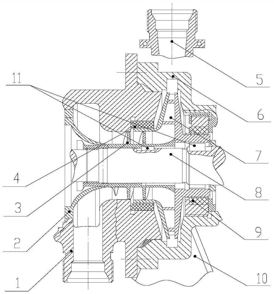
[0029] The invention utilizes the rotation of the impeller to generate high-speed fluid, and then converts the kinetic energy of the flowing liquid into pressure energy through the diffusion effect of the pump casing 6 and the outlet pipe 5, thereby generating high-pressure liquid to ensure the fuel supply of the engine and the combustion inlet pressure requirements. The specific speed of the pump device designed by adopting the invention is only 24, which belongs to the special type pump with ultra-low specific speed. The working medium is unsymmetrical dimethylhydrazine. Under the design flow rate, the medium head can reach 12.6MPa. The structure size of the present invention is light in weight. This type of fuel pump device has passed the test of the engine test and fully meets the system and structure requirements of the upper engine.

[0030] The present invention will be further described in detail below in conjunction with the accompanying drawings and specific embodime...


PUM


Abstract

The invention discloses an ultra-low specific speed centrifugal pump device. The ultra-low specific speed centrifugal pump device includes a spiral blade, a centrifugal impeller, a transmission shaft,and a shell body, wherein the centrifugal impeller sleeves the transmission shaft, and the spiral blade is arranged at an inlet of the centrifugal impeller; a spiral line runner is formed between thespiral blade and the centrifugal impeller; the shell body sleeves the centrifugal impeller on the outside and the transmission, and a cavity is formed between the shell body and the transmission shaft; an inlet and an outlet are formed in the shell body in the radial direction of the transmission shaft; the end surface of an inlet of the centrifugal impeller towards to the cavity; and the cavitycommunicates with an external fuel storage box through the inlet of shell body, and an outlet of the centrifugal impeller is connected with a burning chamber of an external engine. The ultra-low specific speed centrifugal pump device has the advantages of having small structural size, light weight, high lift, low specific speed, and unsymmetrical dimethylhydrazine corrosion resistance, good anti-cavitation performance, high efficiency and the like; and the ultra-low specific speed centrifugal pump device can be widely used in upper stage small thrust pumping-pressure liquid-propellant rocket engines, and can used in the field of energy power with small flow and high exit pressure at the same time.

Description

technical field [0001] The invention relates to an ultra-low specific speed centrifugal pump device, in particular to a fuel booster pump suitable for liquid rocket engines, which can be used in liquid rocket engine propellant supply systems and related energy and power fields. Background technique [0002] As the heart of the liquid rocket engine, the turbo pump has the characteristics of high temperature, high pressure, high speed and corrosive medium. As the core component of the liquid rocket engine propellant supply system, the fuel pump device needs to have high cavitation resistance on the one hand, and work without cavitation at the lowest possible pump inlet pressure, which is beneficial to the weight of the rocket propellant tank. Reduce and increase the payload; on the other hand, as the liquid rocket engine develops towards a higher chamber pressure, the pump supply system must increase the pressure from the tank at a given flow rate and meet the high pressure re...

Claims


Application Information

Patent Timeline
Patent Type & Authority Patents(China)
IPC IPC(8): F04D13/12F04D29/22F04D29/18F04D29/02F04D29/42F04D29/52F04D29/16F04D29/66F02K9/46
Inventor 赵瑞勇刘军年白东安徐楠安莎叶树波
Owner XIAN AEROSPACE PROPULSION INST
Why Eureka
Try Eureka