
Multi-camera standard machine for defect detection of backlight module

A backlight module and defect detection technology, which is applied in optics, nonlinear optics, instruments, etc., can solve the problems that manual detection cannot feed back real-time detection accurate results, cannot establish a unified standard for detection accuracy, and cannot adjust the manufacturing process in time. , to achieve the effect of reducing labor cost and time cost, improving manufacturing process and avoiding uneven quality

Active Publication Date: 2019-06-14
WUHAN JINGLI ELECTRONICS TECH +1
View PDF5 Cites 9 Cited by
  • Summary
  • Abstract
  • Description
  • Claims
  • Application Information

AI Technical Summary

Problems solved by technology

[0004] At present, the most commonly used method for backlight module detection in the industry is manual detection. This method is not only labor-intensive, but also low in detection efficiency.
What's more, due to the existence of visual differences among inspectors, it is impossible to formulate a unified standard for inspection accuracy, and it is difficult to guarantee product quality
In addition, manual inspection cannot feed back accurate results of real-time inspection, and cannot adjust the manufacturing process in time to improve the yield rate, resulting in low overall production capacity

Method used


Image

  • Multi-camera standard machine for defect detection of backlight module
  • Multi-camera standard machine for defect detection of backlight module
  • Multi-camera standard machine for defect detection of backlight module

Examples


Embodiment Construction

[0031] In order to make the object, technical solution and advantages of the present invention clearer, the present invention will be further described in detail below in conjunction with the accompanying drawings and embodiments. It should be understood that the specific embodiments described here are only used to explain the present invention, not to limit the present invention. In addition, the technical features involved in the various embodiments of the present invention described below can be combined with each other as long as they do not constitute a conflict with each other.

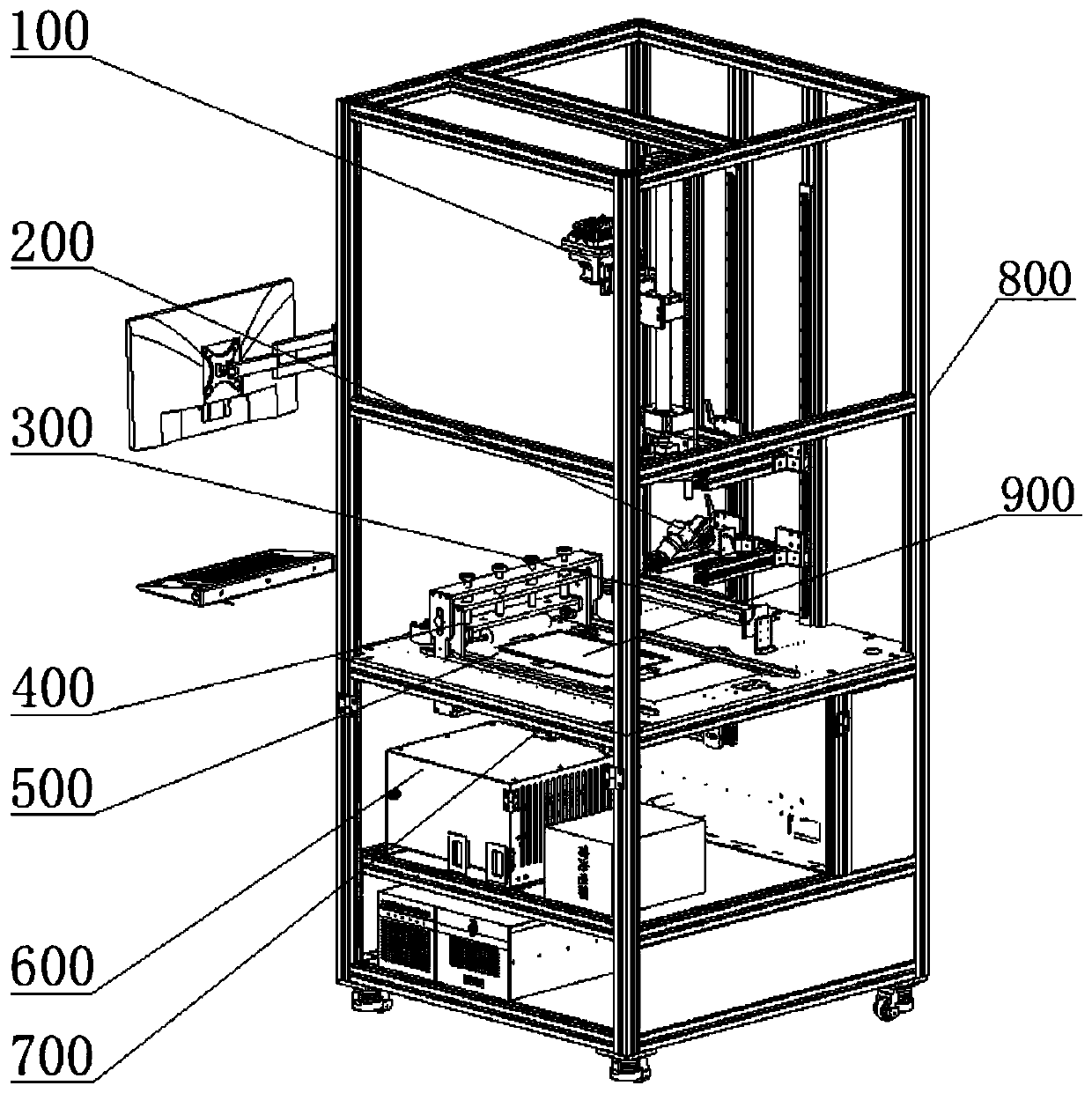
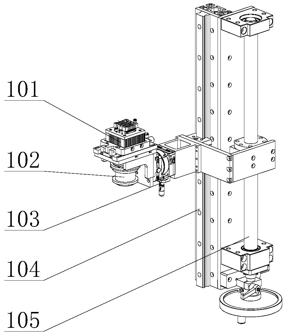
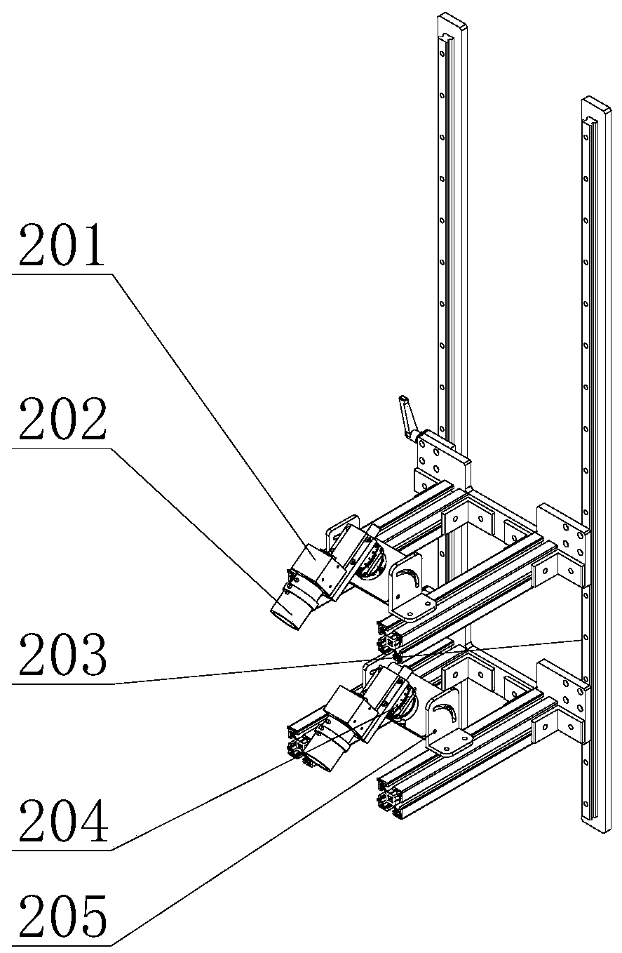
[0032] Such as Figure 1 to Figure 6 As shown, a multi-camera standard machine for defect detection of a backlight module (ie, BLU) includes a frame 800 and a fixture module 500, an automatic code reading module 700, and a dust removal module that are jointly installed on the frame 800 400, side light source lighting module 300, camera detection module and automatic optical detection module 600...


PUM


Abstract

The invention discloses a multi-camera standard machine for defect detection of a backlight module. The multi-camera standard machine comprises a rack, a tool module, an automatic code-reading module,a side light source illumination module, a camera detection module, a dedusting module and an automatic optical detection module, the tool module comprises a tool, a crimping member and a cylinder, the automatic code-reading module is used for reading a bar code pasted on the backlight module and transmitting the information to the automatic optical detection module, the dedusting module is usedfor dedusting the surface of the backlight module, the camera detection module comprises a fin-tuning slide table assembly and a camera, the camera shoots the backlight module, converts an obtained optical image to a digital signal and transmits the digital signal to the automatic optical detection module, and the automatic optical detection module performs analysis and comparison with a saved standard image so that defect detection of the backlight module is realized and whether the backlight module is qualified is determined. According to the multi-camera standard machine, the accuracy and the efficiency of defect detection of the backlight module and the yield of the backlight module of the whole production line are improved, and the labor and time costs are greatly reduced.

Description

technical field [0001] The invention belongs to the field of liquid crystal module backlight detection facilities, and more specifically relates to a multi-camera standard machine used for backlight module defect detection. Background technique [0002] The backlight module is one of the key components of the LCD panel. The function is to supply sufficient brightness and evenly distributed light source so that it can display images normally. Backlight modules have been widely used in various electronic products and modern information equipment such as personal digital assistants due to their advantages of light weight, thin thickness, and low power consumption. [0003] As digitalization and informatization become more and more obvious, backlight modules play an increasingly critical role, accompanied by fierce market competition, and users' requirements for the quality of backlight modules are also constantly improving, which prompts backlight Module manufacturers must pa...

Claims


Application Information

Patent Timeline
Patent Type & Authority Applications(China)
IPC IPC(8): G02F1/13
Inventor 易洁杜彪
Owner WUHAN JINGLI ELECTRONICS TECH
Learn More