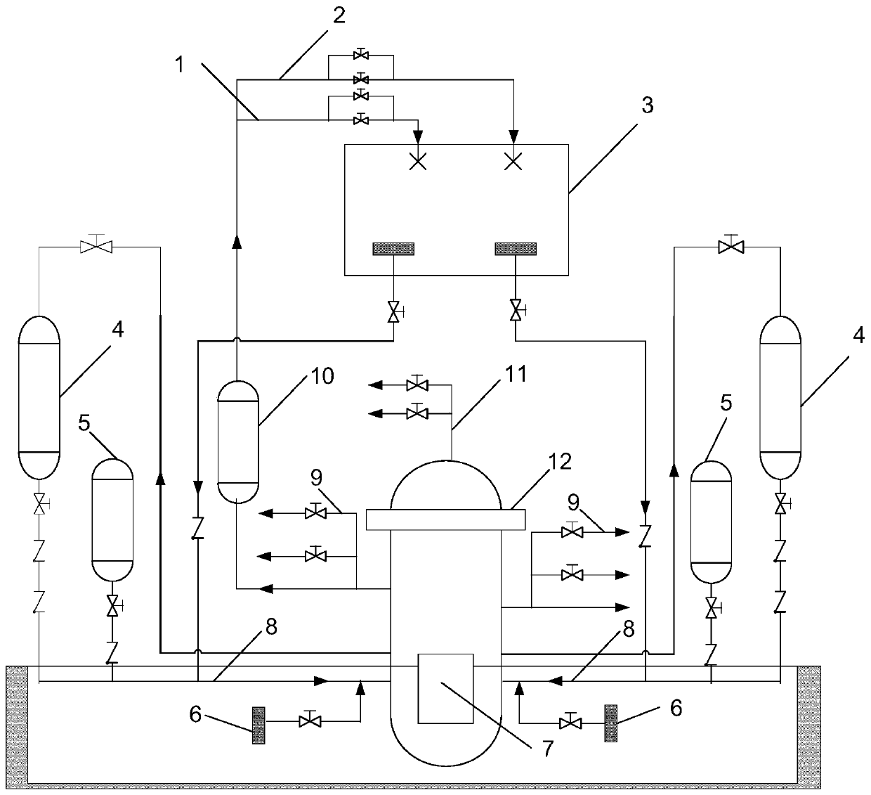
Long-term cooling system for loss-of-coolant accident during isolation failure of modular small reactor containment
A water loss accident and cooling system technology, used in cooling devices, reactors, nuclear power generation, etc., can solve the problems of long-term core cooling and the inability of the cooling system to achieve water loss accidents, etc., to reduce steam resistance, long-term effective cooling, and mitigation. effect of stress
- Summary
- Abstract
- Description
- Claims
- Application Information
AI Technical Summary
Problems solved by technology
Method used
Image
Examples
Embodiment 1
[0039] Such as figure 1 As shown, the long-term cooling system for a loss of water accident when the isolation of the modular small reactor containment fails includes a primary cooling circuit, a secondary cooling circuit and a tertiary cooling circuit. The primary cooling circuit is the core make-up water tank 4 and the pressure The circuit formed between the containers 12, the boron-containing water in the core make-up water tank 4 is directly injected into the pipeline 8 through the pressure vessel and enters the pressure vessel 12 to supplement the boron-containing water to the core 7, and the boron-containing water in the pressure vessel 12 is returned through the pipeline. In the core makeup water tank 4, the primary cooling circuit also includes a safety injection tank 5, and the secondary cooling circuit is a circuit formed between the built-in refueling water tank 3 and the pressure vessel 12, and the built-in refueling water tank 3 The boron-containing water is direc...
Embodiment 2
[0045] Such as figure 1 As shown, this embodiment is based on Embodiment 1. The tertiary cooling circuit also includes a stack top exhaust pipeline 11 arranged at the top of the pressure vessel 12, and the steam generated by the core 7 passes through the third-level pipeline 9 of the pressure relief system and the stack. The top exhaust pipeline 11 is discharged into the containment at the same time; the stack top exhaust pipeline 11 is directly connected to the top exhaust valve on the top of the pressure vessel 12. A liquid level sensor is installed in the built-in refueling water tank 3, and the liquid The level sensor and the exhaust valve at the top of the pile are all connected to the controller in communication, and the controller is also connected to the pit recirculation isolation valve 13 in communication. Trigger "open pit recirculation isolation valve 13" and "open stack top exhaust valve"; two exhaust pipes are arranged in parallel at the outlet end of the stack t...
Embodiment 3
[0048] Such as figure 1 As shown, this embodiment is based on Embodiment 1 or Embodiment 2. The water inlet of the pipeline where the pit recirculation isolation valve is located is provided with a filter screen 6; the safety injection tank 5 is directly injected into the pipeline 8 and the pressure vessel through the pressure vessel 12 connected, when the system pressure is lower than the initial pressure of the safety injection tank, the boron-containing water in the safety injection tank is injected into the core under the action of nitrogen pressure; the first stage pipe 1 of the automatic pressure relief system and the first stage pipe 1 of the automatic pressure relief system The secondary pipeline 2 is led out from the top of the pressurizer 10 and is connected to the built-in refueling water tank 3; the built-in refueling water tank 3 is arranged above the pressure vessel 12.
PUM
 Abstract
Description
Claims
Application Information
 - R&D
- Intellectual Property
- Life Sciences
- Materials
- Tech Scout
- Unparalleled Data Quality
- Higher Quality Content
- 60% Fewer Hallucinations
Browse by: Latest US Patents, China's latest patents, Technical Efficacy Thesaurus, Application Domain, Technology Topic, Popular Technical Reports.
© 2025 PatSnap. All rights reserved.Legal|Privacy policy|Modern Slavery Act Transparency Statement|Sitemap|About US| Contact US: help@patsnap.com

