
P-type PERC double-side solar cell alignment printing method, preparation method and battery

A solar cell and alignment printing technology, applied in the field of solar cells, can solve the problems of affecting the performance of the cell, unable to realize the accurate connection and separation of the back aluminum grid line and the back electrode bus line, etc., so as to reduce the defect rate, effectively connect, The effect of low production cost

Active Publication Date: 2019-06-14
TIANJIN AIKO SOLAR ENERGY TECH CO LTD +1
View PDF6 Cites 3 Cited by
  • Summary
  • Abstract
  • Description
  • Claims
  • Application Information

AI Technical Summary

Problems solved by technology

However, this printing method has the following disadvantages: in actual printing, the back aluminum grid line can cover the back laser groove area, but it cannot realize the accurate connection between the back aluminum grid line and the back electrode main grid line
[0007] This is because: the printing of the back aluminum grid line is to capture the Mark point on the laser groove pattern by the camera to achieve the alignment of the back aluminum grid line and the laser groove pattern, but the laser groove pattern is determined by the setting of the laser equipment. It is located in the center of the silicon wafer, and the back silver electrode is printed by manually adjusting the screen to position the back electrode main grid screen pattern in the center of the silicon wafer. Due to the positioning of the laser groove pattern of the back laser equipment and the manual adjustment of the back electrode There is an error between the positioning of the main grid pattern, which leads to the separation of the connection between the back aluminum grid line printed on the back of the silicon wafer and the back electrode main grid line, thus affecting the performance of the battery

Method used


Image

  • P-type PERC double-side solar cell alignment printing method, preparation method and battery
  • P-type PERC double-side solar cell alignment printing method, preparation method and battery
  • P-type PERC double-side solar cell alignment printing method, preparation method and battery

Examples


Embodiment Construction

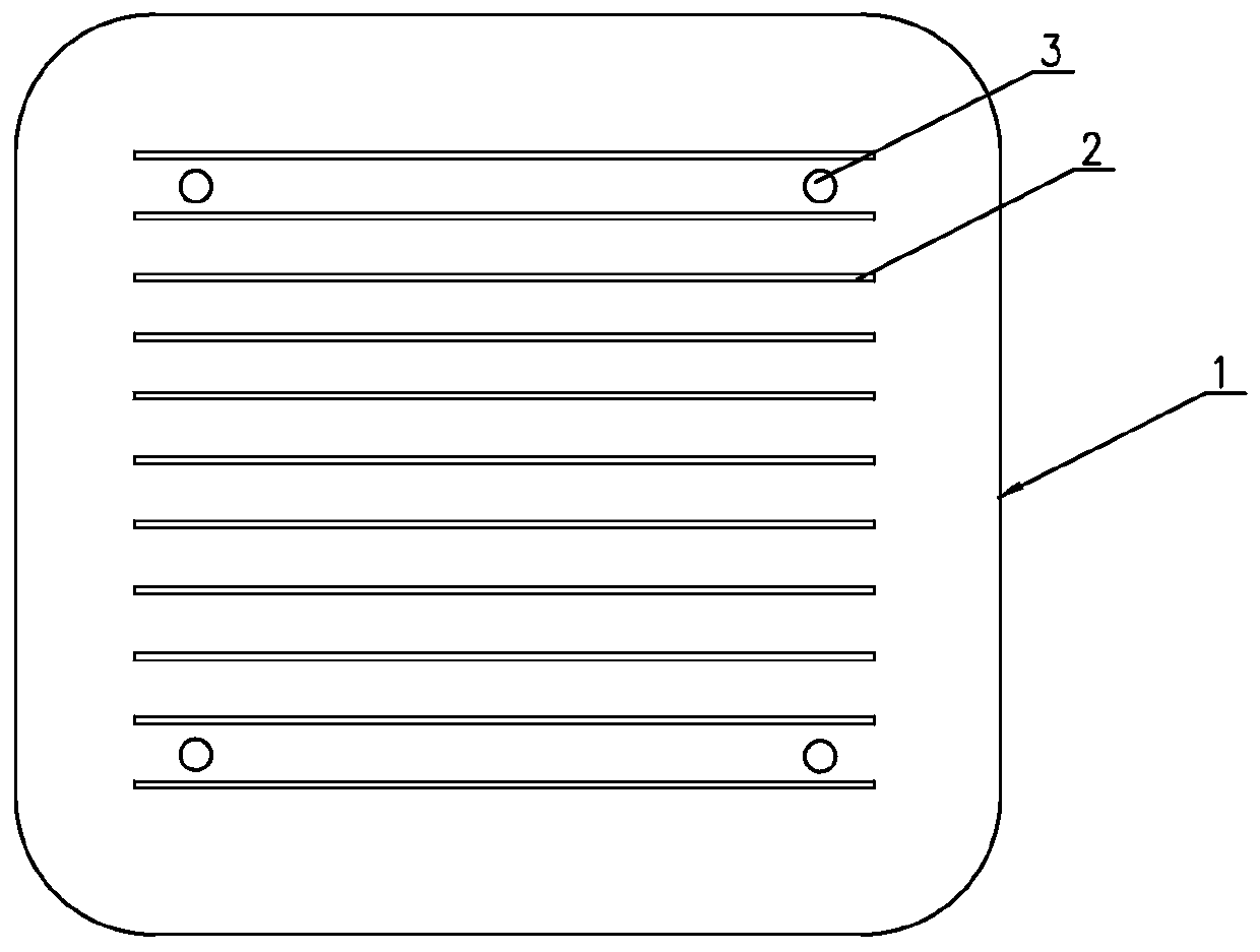
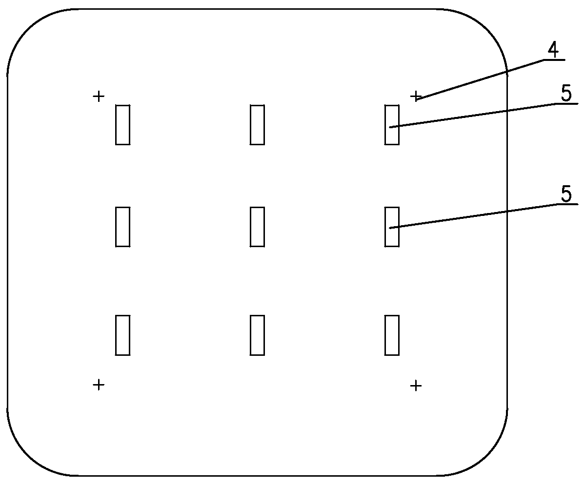
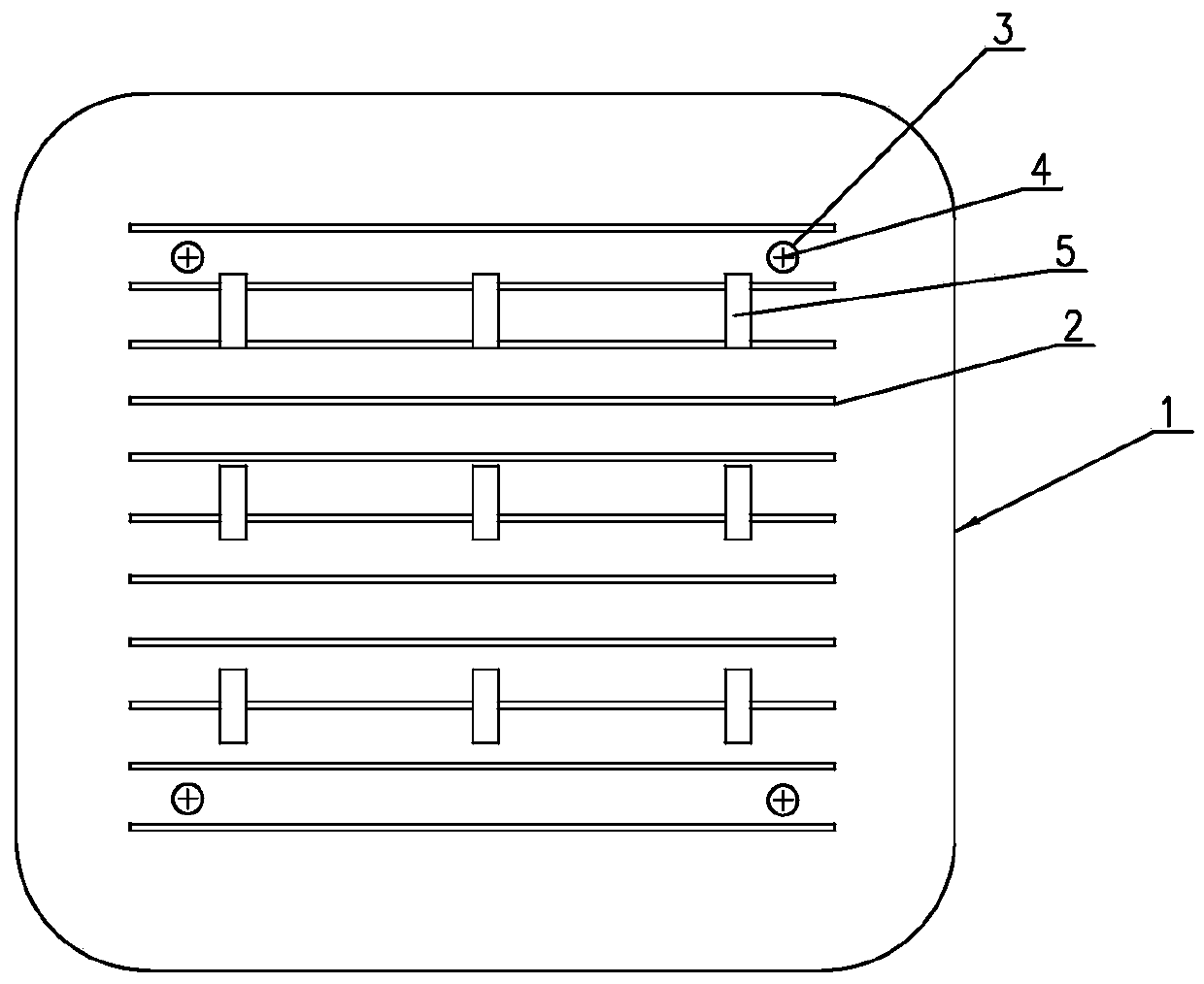
[0045] The invention relates to a P-type PERC double-sided solar cell alignment printing method. In the process of sequentially manufacturing the back laser grooved area, the back electrode main grid line and the back aluminum grid line on the silicon wafer, firstly on the back laser groove pattern Set the Mark1 point, and make the backside laser groove area with the Mark1 point on the silicon wafer, then set the Mark2 point on the back busbar screen, and print the back pole busbar with the Mark2 point on the silicon wafer line; then, use the Mark1 point on the silicon wafer to adjust the position of the silicon wafer through the three parameters of X (horizontal axis), Y (vertical axis), and θ (angle), so that the laser grooved area on the back is aligned with the back aluminum grid line Align the back aluminum grid line on the screen plate with the back aluminum grid line on the back aluminum grid line screen plate and the back electrode main grid line by adjusting the positi...


PUM


Abstract

A P-type PERC double-side solar cell alignment printing method, a preparation method and a battery are disclosed. A Mark 1 point is arranged on a back laser slot pattern, a back laser slot region withthe Mark 1 point is made on a silicon wafer, a mark 2 point is arranged on a back pole main gate line screen plate, and a back pole main gate line with the Mark 2 point is printed on the silicon wafer; the Mark 1 point on the silicon wafer is used, by adjusting the position of the silicon wafer, the back laser slot region is aligned with the back aluminum gate line on the back aluminum gate linescreen plate, and the back aluminum gate line on the back aluminum gate line screen plate is aligned with the back main gate line by moving the silicon wafer transversely by using the Mark 2 point, and the back aluminum gate line is printed, so that the back aluminum gate line covers the back laser slot region and is connected with the main gate line. The invention ensures the effective connectionbetween the back aluminum gate line of the silicon wafer and the back electrode main gate line, avoids the disconnection between the back aluminum gate line and the back electrode main gate line, andeffectively reduces the defective rate of the double-sided PERC solar cell.

Description

technical field [0001] The present invention relates to solar cell technology, in particular to a method for para-position printing of a P-type PERC double-sided solar cell, and also to a method for preparing a P-type PERC double-sided solar cell using the para-position printing method, and to using the preparation method to prepare P-type PERC bifacial solar cells. Background technique [0002] A crystalline silicon solar cell is a device that effectively absorbs solar radiation energy and converts light energy into electrical energy by using the photovoltaic effect. When sunlight shines on the semiconductor P-N junction, new hole-electron pairs will be formed. Under the action of the electric field of the P-N junction, the holes flow from the N region to the P region, and the electrons flow from the P region to the N region. After the circuit is turned on A current is formed. [0003] The back of the conventional battery is equipped with a back silver electrode and an al...

Claims


Application Information

Patent Timeline
IPC IPC(8): H01L31/18H01L31/068H01L31/0224
CPCY02E10/547Y02P70/50
Inventor 林纲正方结彬何达能陈刚
Owner TIANJIN AIKO SOLAR ENERGY TECH CO LTD
Learn More