IPMSM position observation method and system based on rotary high-frequency injection method, and driving system

A high-frequency injection, high-frequency response technology, applied in control systems, vector control systems, motor generator control, etc., can solve the problems of limiting motor speed adaptability, affecting the accurate and comprehensive provision of phase error compensation

Active Publication Date: 2019-06-14
HEFEI UNIV OF TECH
View PDF6 Cites 11 Cited by
  • Summary
  • Abstract
  • Description
  • Claims
  • Application Information

AI Technical Summary

Problems solved by technology

However, the extraction scheme in the static coordinate system limits its adaptability to the motor speed
When the motor is running, due to the difference in the frequency of the positive and negative sequence components of the high-frequency response current in the stationary coordinate system, the corresponding delay effects will also be different, which affects the accuracy of the phase error compensation of the negative sequence current through the positive sequence current phase information. Anyway, the scheme of the compensation angle is susceptible to noise interference
[0007] To sum up, none of the existing technologies can comprehensively provide a method for implementing the rotary high-frequency injection method to effectively eliminate the influence of digital control control delay and filter delay at zero and low speeds while taking into account better dynamic performance. Methods

Method used


Image

  • IPMSM position observation method and system based on rotary high-frequency injection method, and driving system
  • IPMSM position observation method and system based on rotary high-frequency injection method, and driving system
  • IPMSM position observation method and system based on rotary high-frequency injection method, and driving system

Examples


Embodiment Construction

[0094] The embodiments of the present invention are described in detail below. This embodiment is implemented on the premise of the technical solution of the present invention, and detailed implementation methods and specific operating procedures are provided, but the protection scope of the present invention is not limited to the following implementation example.

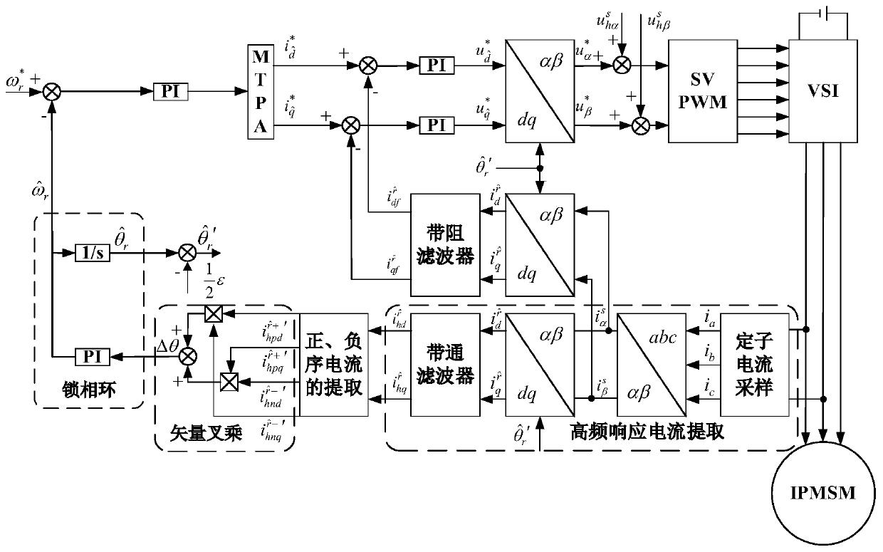
[0095] The IPMSM (Internal Permanent Magnet Synchronous Motor) rotating high-frequency injection method position observation method based on the demodulation of the rotating coordinate system provided by the present invention is applied in figure 1 In the interior permanent magnet synchronous motor drive system shown.

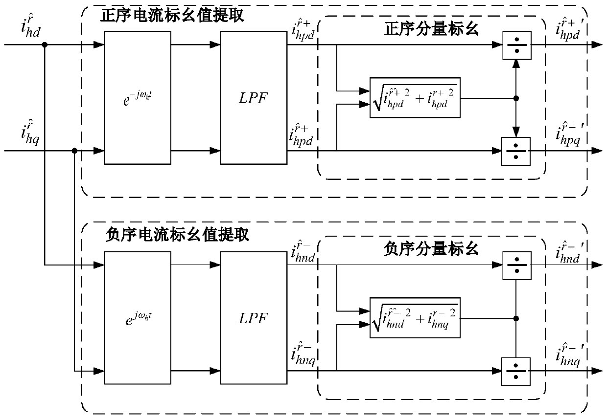
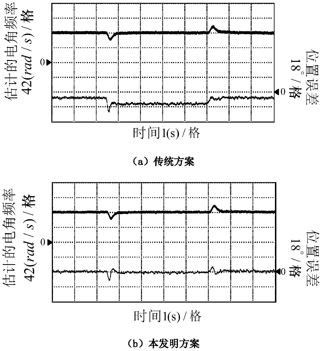
[0096] see figure 1 ~Figure (4), the present embodiment is based on the IPMSM rotating high-frequency injection method position observation method demodulated by the rotating coordinate system according to the following steps:

[0097] Step 1, after the motor completes the initial position detecti...


PUM


Abstract

The invention discloses an IPMSM position observation method based on a rotary high-frequency injection method. The method comprises the following steps that a high-frequency voltage signal is injected into a motor static alpha beta coordinate system after the motor finishes initial position detection; a stator current sampling module is used for performing sampling to obtain three-phase currentsof the motor, and conversion is carried out to obtain an estimated d-q coordinate axis; namely, target currents which are formulas as shown in the specification in a shafting which is a formula as shown in the specification; the target currents which are formulas as shown in the specification are subjected to band-pass filter extraction to obtain high-frequency response currents which are formulasas shown in the specification in a coordinate system which is a formula as shown in the specification; the positive sequence components of the high-frequency response currents which are formulas as shown in the specification in the axis of a formula which is as shown in the specification are extracted through transformation of coordinates and a low-pass filter, and the positive sequence current component per-unit unit processing is carried out; the negative sequence components of the high-frequency response currents which are formulas as shown in the specification in the axis of a formula which is as shown in the specification are extracted through transformation of coordinates and a low-pass filter, and the negative sequence current component per-unit value processing is carried out; andthe obtained high-frequency positive sequence current per-unit value and the high-frequency negative sequence current per-unit value are subjected to vector fork multiplication, and the estimated motor rotating speed and position are obtained. The invention further provides an observation system and an IPMSM driving system. The method has the advantages that no matter whether the IPMSM driving system runs at zero speed or a low speed, relatively high position observation precision is achieved.

Description

technical field [0001] The invention relates to the field of permanent magnet synchronous motor control, in particular to an IPMSM position sensorless control strategy based on a high-frequency injection method. Background technique [0002] In recent years, the advantages of interior permanent magnet synchronous motors (IPMSM) in terms of power density and efficiency have made them widely used. Vector control is the mainstream control scheme of permanent magnet synchronous motor, and its decoupling control characteristics are beneficial to the improvement of system control performance. The accurate acquisition of the rotor flux position is the premise of the decoupling control of the vector control system. Although the installation of mechanical sensors such as photoelectric encoders and resolvers can more accurately detect the speed signal. However, on the one hand, in places with strong vibrations such as electric vehicles and wind power generation, it is difficult to g...

Claims


Application Information

Patent Timeline
Patent Type & Authority Applications(China)
IPC IPC(8): H02P21/18H02P21/24H02P25/022
Inventor 杨淑英刘善宏谢震张兴
Owner HEFEI UNIV OF TECH
Why Eureka
Try Eureka