
A Sensorless Control Method for Periodic Complementary High Frequency Square Wave Injection

A control method and sensor technology, applied in control systems, generator control, motor control, etc., can solve problems such as rotor estimated position offset errors, and achieve the effects of eliminating rotor estimated position offset errors and high rotor position observation accuracy

Active Publication Date: 2022-06-24
HARBIN INST OF TECH
View PDF4 Cites 0 Cited by
  • Summary
  • Abstract
  • Description
  • Claims
  • Application Information

AI Technical Summary

Problems solved by technology

[0006] In view of the high-frequency signal injection method used in the existing motor position sensorless control, due to the influence of inductive cross-coupling factors, there is an offset error in the estimated position of the rotor. The present invention provides a sensorless control with periodic complementary high-frequency square wave injection. method

Method used


Image

  • A Sensorless Control Method for Periodic Complementary High Frequency Square Wave Injection
  • A Sensorless Control Method for Periodic Complementary High Frequency Square Wave Injection
  • A Sensorless Control Method for Periodic Complementary High Frequency Square Wave Injection

Examples


specific Embodiment approach 1

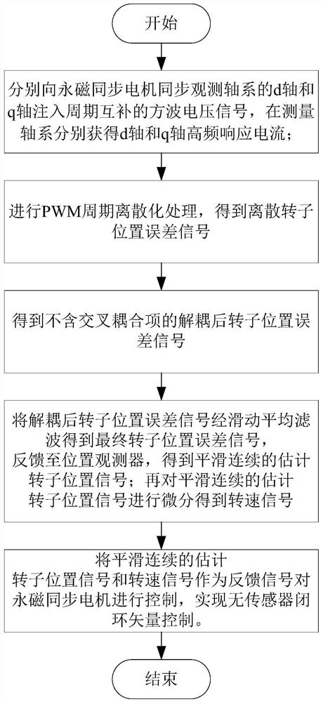
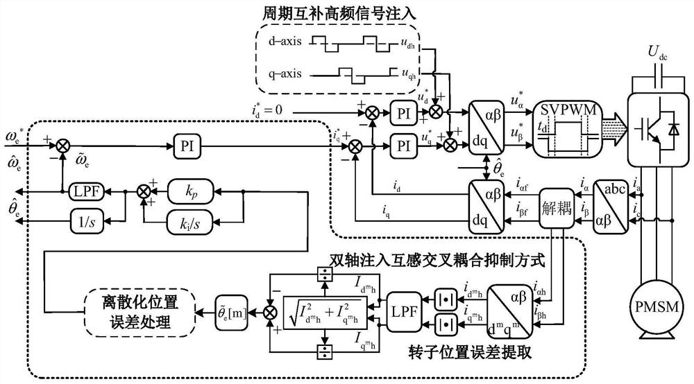
[0048] Specific implementation mode 1. Combination figure 1 and figure 2 As shown, the present invention provides a sensorless control method for periodic complementary high-frequency square wave injection, including,

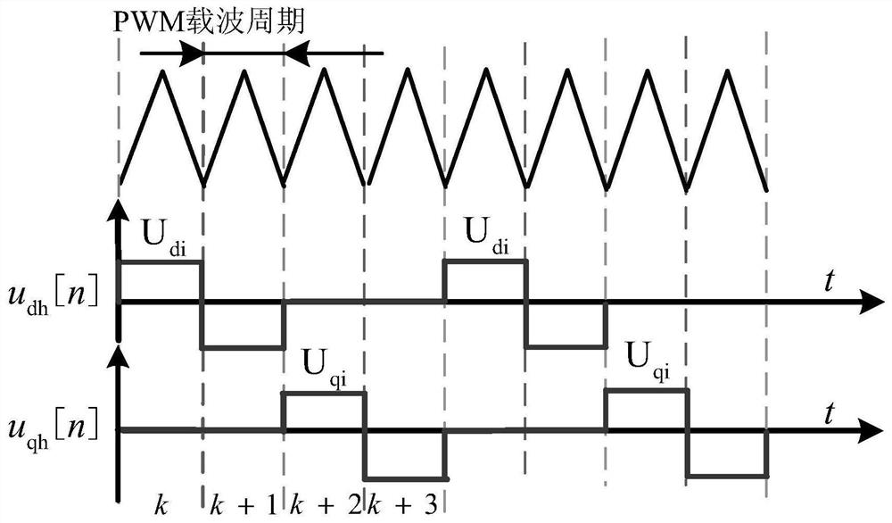
[0049] Each injection pulse cycle is divided into two stages, the first stage injects a square wave voltage signal to the d axis, and the second stage injects a square wave voltage signal to the q axis; the periods of the two phases of the square wave voltage signal are complementary;

[0050] In the injection pulse period, the periodic complementary square wave voltage signals are respectively injected into the d-axis and q-axis of the permanent magnet synchronous motor synchronous observation shaft system, and the high-frequency response currents of the d-axis and q-axis are respectively obtained in the measurement shaft system; for the d-axis Discretize the PWM cycle of the high-frequency response current to obtain the first-stage discrete rotor position e...


PUM


Abstract

The invention relates to a sensorless control method for periodic complementary high-frequency square wave injection, which belongs to the technical field of motor position sensorless control. The invention aims to solve the problem that there is an offset error in the estimated position of the rotor due to the influence of inductive cross-coupling factors in the high-frequency signal injection method used in the existing motor position sensorless control. Including: respectively injecting periodic complementary square wave voltage signals to the d-axis and q-axis of the permanent magnet synchronous motor synchronous observation shaft system, obtaining the high-frequency response current of the d-axis and q-axis, performing PWM cycle discretization processing, and obtaining two-stage Discrete the rotor position error signal, and obtain the decoupled rotor position error signal without cross-coupling items, and then obtain the final rotor position error signal through moving average filtering, and further obtain smooth and continuous estimated rotor position signal and speed signal as the feedback signal Control the permanent magnet synchronous motor. The invention can obtain higher rotor position observation accuracy.

Description

technical field [0001] The invention relates to a sensorless control method for periodic complementary high-frequency square wave injection, and belongs to the technical field of motor position sensorless control. Background technique [0002] For the control technology of electromagnetic synchronous motor, the most widely used is the vector control technology. The high-performance control of permanent magnet synchronous motors requires accurate rotor position information to achieve magnetic field orientation, and position detection devices, such as photoelectric encoders and incremental code discs, are usually installed at the rotor shaft end. However, these sensors increase the cost and volume of the system, and reduce the reliability and anti-interference ability of the system. By detecting the motor voltage and current signals and estimating the rotor position and speed in combination with the motor model, the sensorless control of the motor can be realized. Therefore,...

Claims


Application Information

Patent Timeline
Patent Type & Authority Patents(China)
IPC IPC(8): H02P21/18H02P21/26H02P6/18H02P6/185H02P25/026H02P27/08
CPCH02P21/18H02P21/26H02P6/183H02P6/185H02P25/026H02P27/08H02P2207/05
Inventor 张国强汪思淳王高林毕广东徐殿国
Owner HARBIN INST OF TECH
Learn More