Liquid-cooling concentrated cooling module

A heat dissipation module and liquid cooling technology, applied in the direction of cooling/ventilation/heating transformation, etc., can solve the problems of large volume, increase heat transfer resistance, etc., achieve the effect of small volume flow, increase power density, and increase product competitiveness

Pending Publication Date: 2019-06-14
上海瑞晟汽车电气系统有限公司
View PDF0 Cites 0 Cited by
  • Summary
  • Abstract
  • Description
  • Claims
  • Application Information

AI Technical Summary

Problems solved by technology

[0003] The conventional water-cooling scheme of the existing electronic control system is: fix the heating power device inside and outside the metal tank, and the metal tank is connected to the water-cooled plate below through the heat-conducting mat

Method used


Image

  • Liquid-cooling concentrated cooling module
  • Liquid-cooling concentrated cooling module
  • Liquid-cooling concentrated cooling module

Examples


Embodiment Construction

[0030] In order to make the object, technical solution and advantages of the present invention clearer, various embodiments of the present invention will be described in detail below in conjunction with the accompanying drawings. However, those of ordinary skill in the art can understand that, in each implementation manner of the present invention, many technical details are provided for readers to better understand the present application. However, even without these technical details and various changes and modifications based on the following implementation modes, the technical solution claimed in each claim of the present application can be realized.

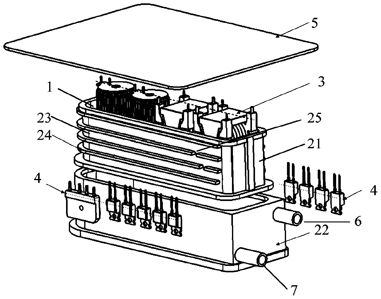
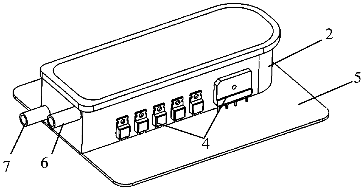
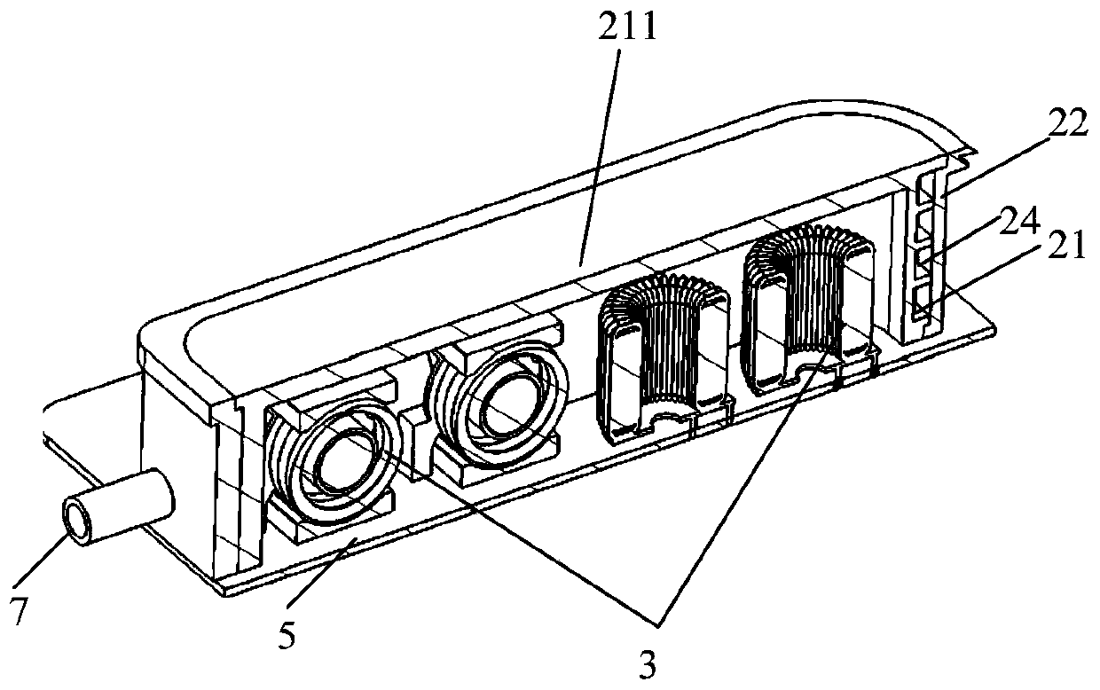
[0031] A preferred embodiment of the present invention relates to a liquid-cooled centralized heat dissipation module, such as Figure 1 to Figure 3 shown, where figure 1 It is the explosion diagram of the liquid-cooled centralized heat dissipation module before assembly; figure 2 It is a schematic diagram of the external...


PUM


Abstract

The invention discloses a liquid-cooling concentrated cooling module. Components needed to be cooled are attached onto wall surfaces (an inner cavity wall and an outer cavity wall) of an inner side and an outer side of a runner cavity, heat generated by the components can be directly caused to a cavity wall of a heat conduction cavity, so that the heat transfer path of the components is greatly shortened, the thermal resistance is reduced, the cooling efficiency is improved, and more heat can be taken way by the liquid-cooling concentrated cooling module under the same power consumption; moreover, the components are arranged in the heat conduction cavity in a concentrated way or are attached onto a part around the heat conduction cavity, so that the product volume can be reduced, the powerdensity is improved, and the product competitiveness is improved; and under the sample condition of heat conduction quantity, the heat transfer path of the liquid-cooling concentrated cooling moduleis short, the volume flowing quantity of a needed heat conduction liquid is smaller, so that the power consumption of external auxiliary equipment can be reduced (such as a water pump for water supply).

Description

technical field [0001] The invention relates to a heat dissipation technology for electric appliances, in particular to a liquid cooling heat dissipation structure for electric appliances. Background technique [0002] Under the trend of increasing integration and power density of electronic control systems in the automotive electronics industry, the heat loss generated by internal devices is increasing. When the heat cannot be dissipated in time, it will seriously affect the reliability and service life of electronic components. This puts forward higher requirements for heat dissipation. An excellent thermal design scheme can not only meet the reliability requirements of the product, but also save more effective space for the car in terms of lightweight and miniaturization, and achieve overall weight reduction. Effect. [0003] The conventional water-cooling scheme of the existing electronic control system is: fix the heating power device inside and outside the metal tank...

Claims


Application Information

Patent Timeline
IPC IPC(8): H05K7/20
Inventor 畅朋政孙胜前
Owner 上海瑞晟汽车电气系统有限公司
Why Eureka
Try Eureka