Underwater gravel base bed laying method

A laying method and foundation bed technology, applied to underwater structures, water conservancy projects, infrastructure projects, etc., can solve the problems of correcting riprap pipes, slow positioning speed, and difficult control of leveling accuracy, so as to ensure accuracy and facilitate Migration, the effect of improving construction efficiency

Pending Publication Date: 2019-06-18
CCCC SECOND HARBOR ENG
View PDF2 Cites 2 Cited by
  • Summary
  • Abstract
  • Description
  • Claims
  • Application Information

AI Technical Summary

Problems solved by technology

The disadvantage of this method is that the cost is extremely expensive, and the pile legs need to be inserted into the groove of the tunnel foundation bed, which has a certain damage to the foundation
[0005] Chinese patent document CN107489154A records a construction method for leveling deep-sea foundation beds, which implements rock throwing through the movement of the hull. The existing problem is that the hull is affected by waves during the movement process, and the construction accuracy is not high.
However, with this scheme, after a construction area is completed, the hull needs to be moved as a whole and repositioned. In the repositioning process, it is necessary to rely on the positioning accuracy of GPS, which has the problems of slow positioning speed and poor positioning accuracy.
Further, it also records the scheme of controlling the balance pipe to expand and contract repeatedly through the hydraulic cylinder to adjust the stroke, but due to the influence of water flow and wind and waves, it is difficult to keep the riprap pipe vertical. Although the inclinometer is recorded in the manual, the It does not record how to correct the inclination of the riprap pipe according to the inclination to ensure the flatness of the foundation bed
Further, since the hydraulic cylinders are located underwater, and each hydraulic cylinder has oil inlet and oil return pipes, it is very difficult to accurately control multiple hydraulic cylinders, and many hydraulic oil pipes make the lifting control of the riprap pipe very troublesome
Furthermore, the above-mentioned document also records that the leveling head is used to scrape the foundation bed, but as the length of the riprap tube increases, the bending deformation of the riprap tube increases, and the leveling accuracy of this solution is difficult to control

Method used


Image

  • Underwater gravel base bed laying method
  • Underwater gravel base bed laying method
  • Underwater gravel base bed laying method

Examples


Embodiment 1

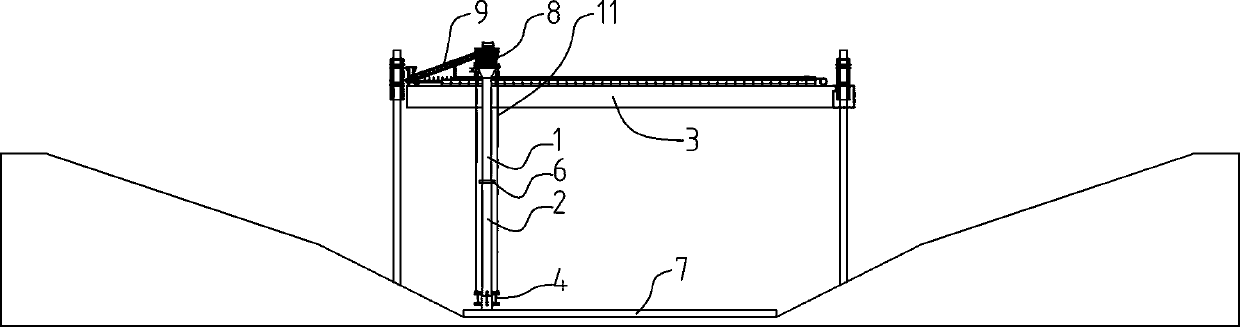
[0063] Such as Figure 2~4 Among them, a method for laying an underwater crushed stone bed, comprising the following steps:

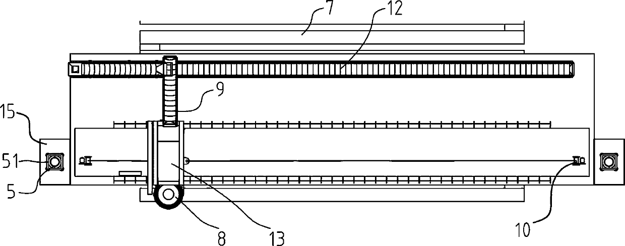
[0064] S1, the hull 3 is provided with a transport trolley 13, the transport trolley 13 is driven by the driving device to slide along the length direction of the hull 3, the transport trolley 13 is provided with a slide pipe, the top of the slide pipe is provided with a feeding port 8, and the slide pipe The bottom is close to the bottom of the water; there is also at least one conveyor belt for feeding the trolley 13;

[0065] S2. The hull moves to the design position through the winch, and uses GPS or Beidou system to locate the position of the chute on the horizontal plane;

[0066] S3, by adjusting the lifting of the chute, control the elevation position of the discharge port at the bottom of the chute;

[0067] S4, the bottom of the chute is provided with a discharge opening adjustment device 4, and an inclination adjustment oil cylinder 42 is a...

Embodiment 2

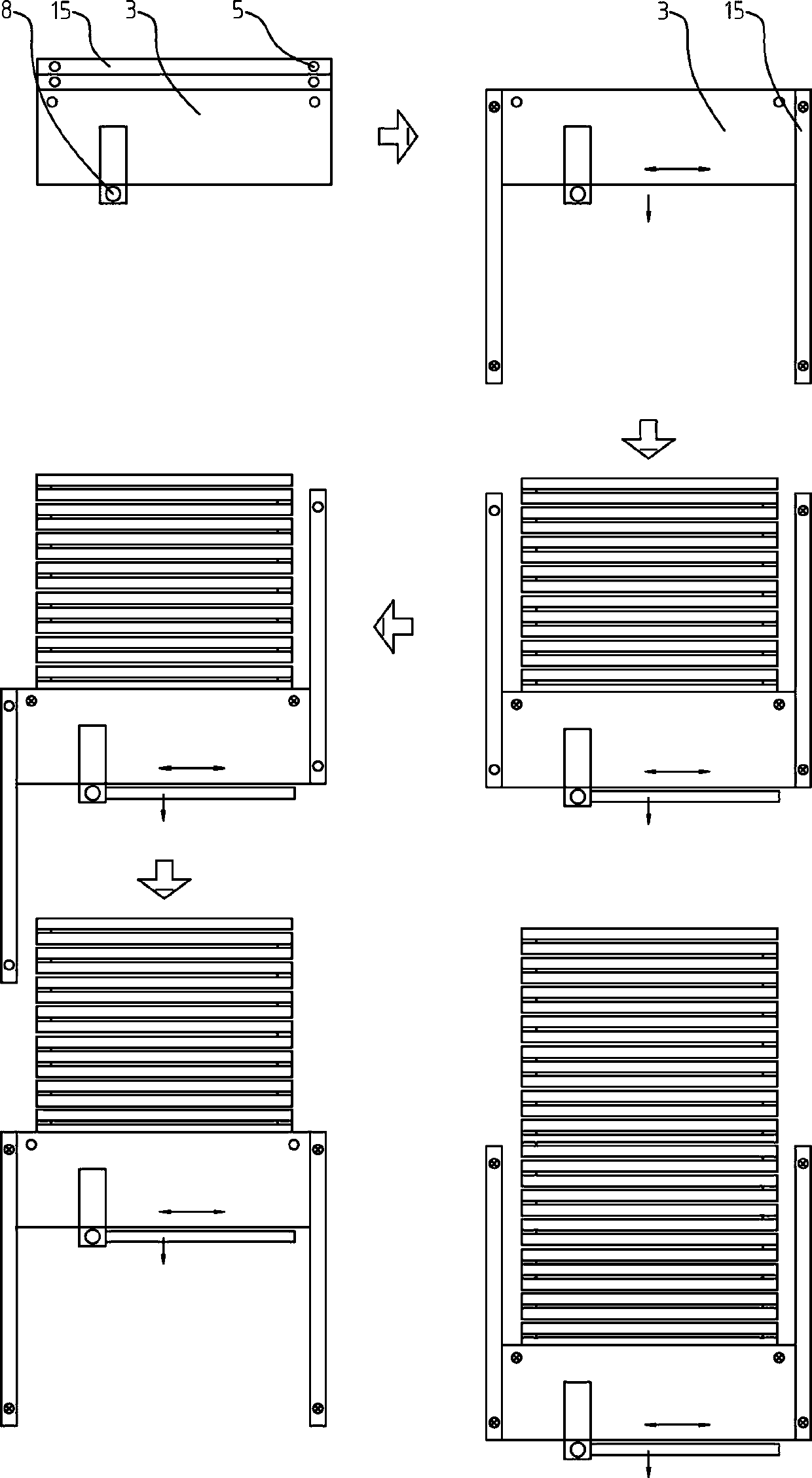
[0072] On the basis of Example 1, the preferred scheme is as figure 2 In step S1, a liftable positioning pile 5 is provided at the bow and stern of the hull 3, and the positioning pile 5 is slidably connected with the hull 3;

[0073] In step S2, the positioning pile 5 is driven into the bottom of the water;

[0074] In step S6, after the construction of one row of crushed stone bed 7 is completed, the hull 3 moves to the position of the next row through the guidance of the positioning pile 5, and then the construction of the crushed stone foundation bed is carried out; relatively sliding.

[0075] After the hull 3 reaches the sliding limit position, the hull 3 is fixed, the spuds 5 are pulled out, and the spuds 5 are slid back to the initial position;

[0076] The continuous laying construction of the underwater crushed stone bed is realized through the above steps. According to this scheme, the winch 10 drives the transport trolley 13 to reciprocate to complete the ripra...

Embodiment 3

[0078] On the basis of Example 2, the preferred scheme is as figure 1 , 5 In ~7, in step S1, the positioning pile 5 is arranged on the floating tank slide rail 15, and at least two positioning pile locking devices 51 are arranged at the positions near the two ends of the floating tank sliding rail 15, and the positioning pile 5 can be lifted and lowered to be arranged on the positioning In the pile locking device 51; the cross section of the positioning pile locking device 51 is a circular structure, an opening is provided on the ring, and a hinged compression block is arranged at the position of the opening. One end of the locking cylinder is hinged with the compression block, and the other end Connected with the ring structure, the first chute 1 is loosened or compressed by the expansion and contraction of the piston rod of the locking cylinder. The construction method of lifting the positioning pile 5 and driving into the bottom of the water belongs to the technology commo...


PUM


Abstract

The invention provides an underwater gravel base bed laying method. The underwater gravel base bed laying method comprises the following steps that a hull is moved to the designed position through a winch, and the position of an articulated chute on the horizontal plane, is positioned by a GPS or a Beidou system; by adjusting rising and falling of the articulated chute, the elevation position of adischarging outlet in the bottom of the articulated chute is controlled; a discharging outlet adjusting device is arranged at the bottom of the articulated chute, a dip angle adjusting oil cylinder is arranged in the discharging outlet adjusting device, and the levelness of the discharging outlet in the lowermost end of the articulated chute is adjusted; the articulated chute is filled with stonethrough a conveying belt, when the stone reaches the set height, a conveying trolley and the articulated chute are driven to slide in the length direction of the hull, the stone flows out from the lower part of the articulated chute, and thus a gravel ridge belt, namely a gravel base bed, is formed; after one row of gravel base bed is constructed, the position of the hull is moved, and the next row of gravel base bed is constructed; and underwater gravel base bed laying construction is achieved through the steps. Riprapping construction of the underwater gravel base bed can be achieved with the high precision and the economical cost.

Description

technical field [0001] The invention relates to the field of underwater engineering construction, in particular to an underwater gravel bed laying method. Background technique [0002] The immersed tube method is a construction method for building tunnels under water. Immersed tube tunnel is an underwater tunnel constructed by floating several prefabricated sections to the sea surface (river surface) site, and sinking and installing them one by one in the dredged foundation trench. In order to avoid local high points of the foundation, the bottom plate of the immersed tube is evenly stressed, and a high-precision leveled gravel cushion is designed between the bottom plate and the foundation as the foundation bed, and a special gravel cushion laying ship with high leveling accuracy is required for construction. [0003] The representative ship is the dynamic positioning straight drop pipe riprap ship "FLINTSTONE" under the DEME group, which is the largest riprap ship in the ...

Claims


Application Information

Patent Timeline
IPC IPC(8): E02D29/073E02D15/10
Inventor 张鸿杨秀礼翟世鸿华晓涛冯先导徐杰程茂林王聪刘修成吴中正夏昊孟奎朱明清
Owner CCCC SECOND HARBOR ENG
Why Eureka
Try Eureka