Thermal barrier coating high temperature erosion detection method

A thermal barrier coating and detection method technology, applied in the field of aero-engines, can solve problems such as difficult detection, low efficiency, and high cost, and achieve scientific and reasonable evaluation, improve detection efficiency, and save detection costs

Active Publication Date: 2019-06-18
XIANGTAN UNIV
View PDF29 Cites 12 Cited by
  • Summary
  • Abstract
  • Description
  • Claims
  • Application Information

AI Technical Summary

Problems solved by technology

[0008] The purpose of the present invention is to provide a detection method for high temperature erosion of thermal barrier coatings. By simulating the high temperature erosion environment under the working condition of the aeroengine, the high temperature erosion detection of thermal barrier coatings is carried out, and according to the samples before and after erosion Calculate the erosion rate of the thermal barrier coating from the mass change, or calculate the ratio of the remaining area of ​​the thermal barrier coating to the initial area of ​​the thermal barrier coat

Method used


Image

  • Thermal barrier coating high temperature erosion detection method
  • Thermal barrier coating high temperature erosion detection method
  • Thermal barrier coating high temperature erosion detection method

Examples


Embodiment 1

[0110] image 3 It is a schematic diagram of the change of the surface morphology of the test piece level sample with the erosion time provided by Example 1 of the present invention.

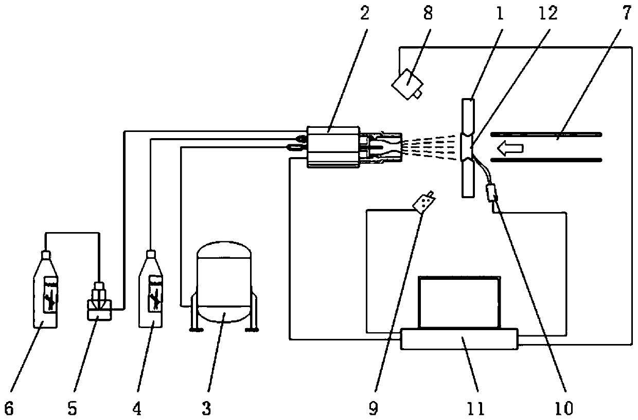
[0111] In this example 1, sample 12 is a test piece-level sample, clamped and fixed at a preset position by clamp 1, kerosene is pressurized to 0.6Mpa by N2, and then the kerosene is atomized by a liquid atomization device to form atomization Kerosene; O with a certain pressure and flow 2 Mix with atomized kerosene to form a fuel gas source, wherein the flow rate of atomized kerosene is 3.0L / h, O 2 The flow rate is 130L / min, O 2 The pressure is 1.05Mpa, O 2 The pressure is 0.2 MPa higher than the pressure of atomized kerosene; adjust the distance between the supersonic spray gun 2 and the sample 12, adjust the angle between the supersonic spray gun 2 and the sample surface to be 90°, and when the sample surface temperature reaches 1100 °C, pass The powder feeder 5 adds Al with a diameter of ...

Embodiment 2

[0114] Figure 4 It is a schematic diagram of the change curve of the erosion rate of the thermal barrier coating on the surface of the test piece-level sample provided by Example 2 of the present invention at different erosion angles with erosion time.

[0115] Please refer to Figure 4 , Figure 4 is a two-dimensional data point diagram based on the erosion rate and erosion time of the thermal barrier coating on the sample surface, where the abscissa is the erosion time and the ordinate is the erosion rate. The two-dimensional data point diagram reflects the change of the erosion rate with the erosion time of the test piece-level samples at different erosion angles.

[0116] The test conditions in this embodiment are when the erosion angles are 60°, 75° and 90° respectively, the average particle diameter of the erosion particles is 60 μm, and the transport rate of the erosion particles is 7 g / min. Perform high-temperature erosion, take multiple erosion time points during ...

Embodiment 3

[0128] Figure 5 It is a schematic diagram of the coating state of the thermal barrier coating on the surface of the blade-level sample during the high-temperature erosion test provided by Example 3 of the present invention.

[0129] Please refer to Figure 5 , the right side of the figure is the supersonic spray gun 2; the left side of the figure is the fixture 1 and the sample 12 installed on the fixture 1, wherein the sample 12 is a blade-level sample, and the black area on the left side of the figure is the heat insulation baffle; The white gas flow column between the sonic spray gun 2 and the sample 12 is the high-temperature flame flow generated by the supersonic spray gun 2 . It can be seen from the figure that due to the different degrees of high temperature erosion in each area of ​​the leaf, on the one hand, the temperature of each area of ​​the leaf is different, resulting in inconsistent colors on the surface of the leaf picture. The color of the area with higher ...


PUM

PropertyMeasurementUnit
Diameteraaaaaaaaaa

Abstract

A thermal barrier coating high temperature erosion detection method is disclosed. The method comprises the following steps of acquiring initial mass of a sample or an initial area of a thermal barriercoating on a sample surface; spraying a high temperature flame flow to the sample surface fixed at a preset position; when a sample surface temperature and the direction of the high temperature flameflow satisfy certain conditions, doping erosion particles into the high temperature flame flow, and carrying out high temperature erosion on the thermal barrier coating on the sample surface; obtaining residual mass of the sample after high temperature erosion or the remaining area of the thermal barrier coating of the sample surface; and calculating an erosion rate of the thermal barrier coatingof the sample surface based on the initial mass and the residual mass of the sample, or calculating a ratio of the remaining area of the thermal barrier coating and the initial area of the thermal barrier coating based on the initial area of the thermal barrier coating on the sample surface and the remaining area of the thermal barrier coating. Through simulating a high temperature erosion environment under a working condition of an aero-engine, high temperature erosion detection is performed on the thermal barrier coating, a reliable basis is provided for the research of a thermal barrier coating material and detection efficiency of the thermal barrier coating is improved.

Description

technical field [0001] The invention relates to the technical field of aero-engines, in particular to a detection method for high-temperature erosion of a thermal barrier coating. Background technique [0002] Thermal barrier coating is a layer of ceramic coating, which is deposited on the surface of high-temperature metals or superalloys. And the interface oxide layer formed during preparation or service is used to protect the base material, so that the engine turbine blade made of it can operate at a high temperature of 1600 °C. The application of thermal barrier coating can not only improve the high temperature corrosion resistance of the substrate, further increase the operating temperature of the engine, but also reduce fuel consumption, improve efficiency, and prolong the service life of hot end components. According to statistics, the global thermal barrier coating market was valued at US$1.286 billion in 2016 and is expected to reach US$2.23 billion by 2024, reachin...

Claims


Application Information

Patent Timeline
IPC IPC(8): G01N3/56
Inventor 朱旺谭振宇杨丽周益春
Owner XIANGTAN UNIV
Why Eureka
Try Eureka