Thermoelectric unit combined control method and system

A technology of combined control and thermal power unit, applied in general control systems, control/regulation systems, adaptive control, etc., can solve the problems of not significantly improved load rate, large pipe diameter, no quick opening function, etc., to eliminate The effect of dynamic energy imbalance and improving variable load rate

Active Publication Date: 2019-06-18
GUODIAN SCI & TECH RES INST
View PDF5 Cites 0 Cited by
  • Summary
  • Abstract
  • Description
  • Claims
  • Application Information

AI Technical Summary

Problems solved by technology

However, because the hydraulic butterfly valve has many disadvantages such as large pipe diameter, quick closing function, no quick opening function, lack of valve positioning, and easy jamming, etc., the load changing rate of the unit has not been significantly improved by using this method.

Method used


Image

  • Thermoelectric unit combined control method and system
  • Thermoelectric unit combined control method and system
  • Thermoelectric unit combined control method and system

Examples


Embodiment Construction

[0056] The core of the present invention is to disclose a combined control method and system of thermoelectric units to increase the load changing rate of thermoelectric units.

[0057] Hereinafter, an embodiment will be described with reference to the drawings. In addition, the examples shown below do not limit the content of the invention described in the claims in any way. In addition, all the contents of the configurations shown in the following embodiments are not limited to be essential to the solution of the invention described in the claims.

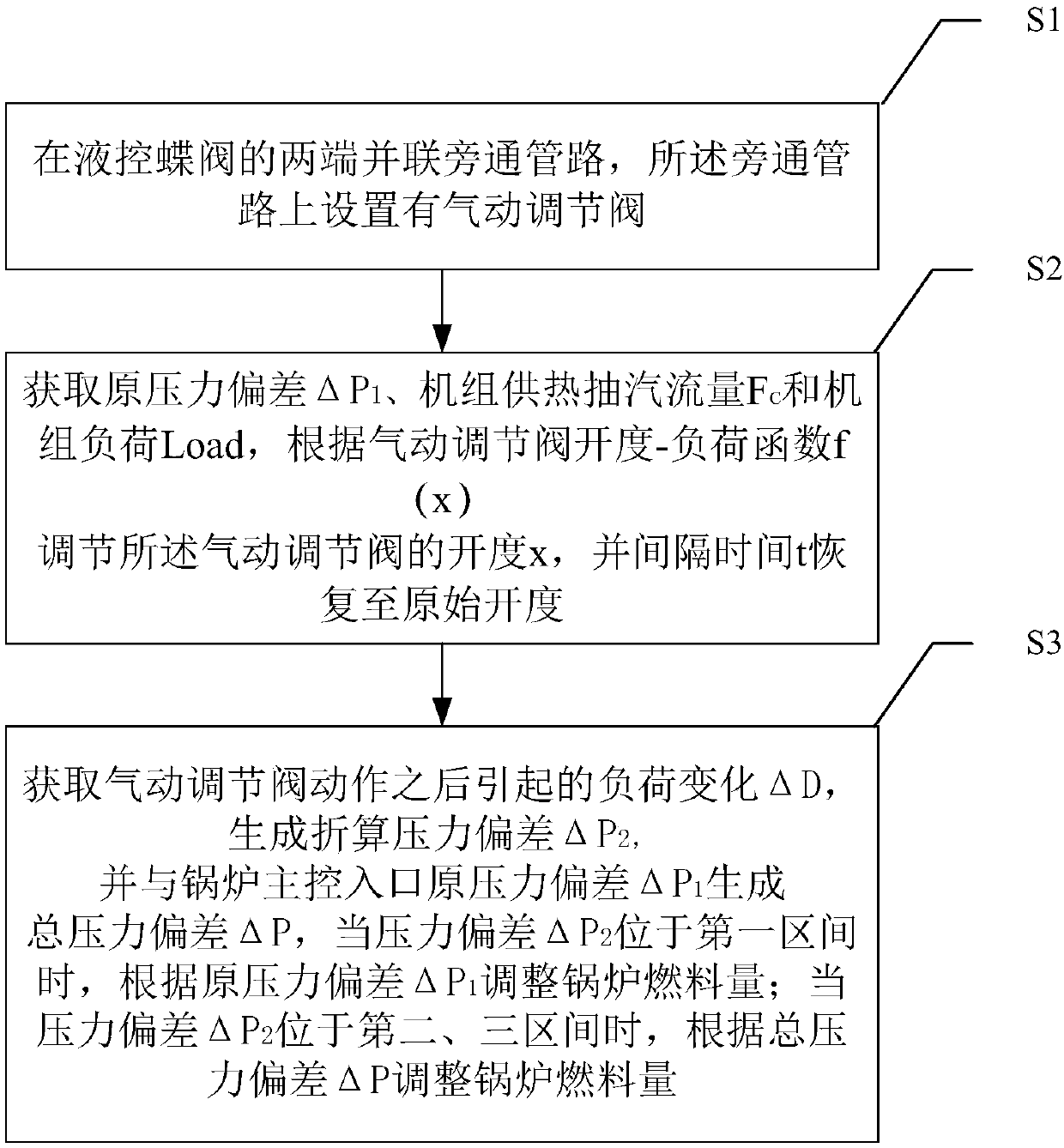
[0058] see figure 1 , the joint control method of the thermoelectric unit includes:

[0059] Step S1: Connect bypass pipelines in parallel at both ends of the hydraulic control butterfly valve, and the bypass pipeline is provided with a pneumatic regulating valve;

[0060] Step S2: Obtain the original pressure deviation ΔP 1 , Unit heating and extraction flow F c and unit load Load, adjust the opening x of the pneumatic regu...


PUM


Abstract

The embodiments of the invention disclose a thermoelectric unit combined control method and system. The action of pneumatic control valve combining control of a thermoelectric unit of the embodimentsof the invention changes energy storage of a steam turbine in a transient-state mode, and thus the unit load and the main steam pressure are changed. Meanwhile, according to the thermoelectric unit combined control method and system, a load change value generated by a pneumatic control valve is converted to a main steam pressure deviation value, sent to the main control entrance of a boiler, and released slowly, coal feed quantity is gradually changed to eliminate pressure deviation, namely, dynamic energy imbalance of the boiler furnace is gradually eliminated. Therefore, according to the thermoelectric unit combined control method, the load changing speed rate of the thermoelectric unit can be improved.

Description

technical field [0001] The present invention relates to the technical field of firepower coordinated control, and more specifically, relates to a combined control method and system for thermoelectric units. Background technique [0002] AGC (auto generate control) is a control method set by the thermal power unit to meet the quality requirements of the grid power supply. AGC is mainly realized through the coordinated control of the steam turbine and boiler of the thermal power unit. Generally, the main steam pressure is controlled by adjusting the coal (powder) supply, and the steam turbine adjusts the door to control the load, so that the unit can quickly respond to the AGC command of the grid. However, the change speed of the AGC command should not be too fast, otherwise, it may take time to adjust the heat storage of the boiler, resulting in excessive deviation of the main steam pressure of the unit, which will affect the load change rate of the unit. [0003] In this co...

Claims


Application Information

Patent Timeline
Patent Type & Authority Applications(China)
IPC IPC(8): G05B13/04
Inventor 陈彦桥李永生刘建民常金旺范国朝谢云辰
Owner GUODIAN SCI & TECH RES INST
Why Eureka
Try Eureka