Bridge inspection method

A bridge and automatic inspection technology, applied in three-dimensional position/channel control, optical test flaws/defects, etc., can solve the problems of poor data acquisition stability, low degree of automation, and heavy workload, so as to ensure safe return and improve automation degree, the effect of reducing difficulty

Inactive Publication Date: 2019-06-18
ZHUZHOU TIMES ELECTRONICS TECH CO LTD
View PDF20 Cites 17 Cited by
  • Summary
  • Abstract
  • Description
  • Claims
  • Application Information

AI Technical Summary

Problems solved by technology

[0019] In view of this, the purpose of the present invention is to provide a bridge inspection method to solve the problem that the existing UAV bridge inspection method mainly relies on manual operation of the UAV to collect bridge surface data, which has a low degree of automation, heavy workload, and difficult data acquisition. Technical problems of poor stability and low security

Method used


Image

  • Bridge inspection method
  • Bridge inspection method
  • Bridge inspection method

Examples


Embodiment 1

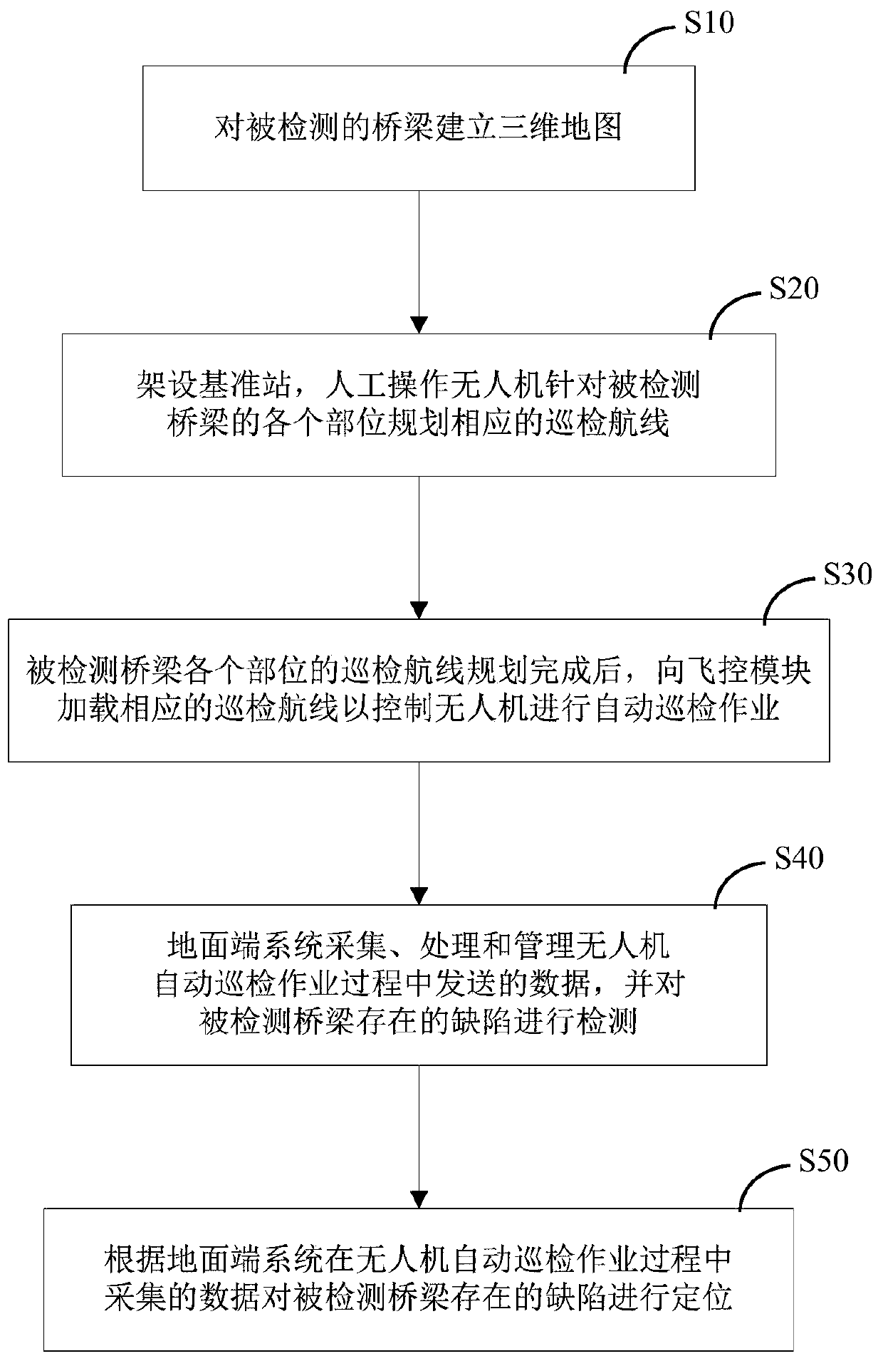
[0094] as attached image 3 As shown, an embodiment of the bridge inspection method of the present invention specifically includes the following steps:

[0095] S10) building a three-dimensional map of the detected bridge;

[0096] S20) set up reference station 4 (such as GNSS-RTK reference station can be adopted, GNSS: Global Navigation Satellite System, the abbreviation of Global Navigation Satellite System; RTK: Real Time Kinematic, the abbreviation of real-time dynamic positioning), the artificially operated UAV 10 targets the Detect the various parts of the bridge and plan the corresponding inspection routes. The structure of the reference station 4 is as attached Figure 15 shown;

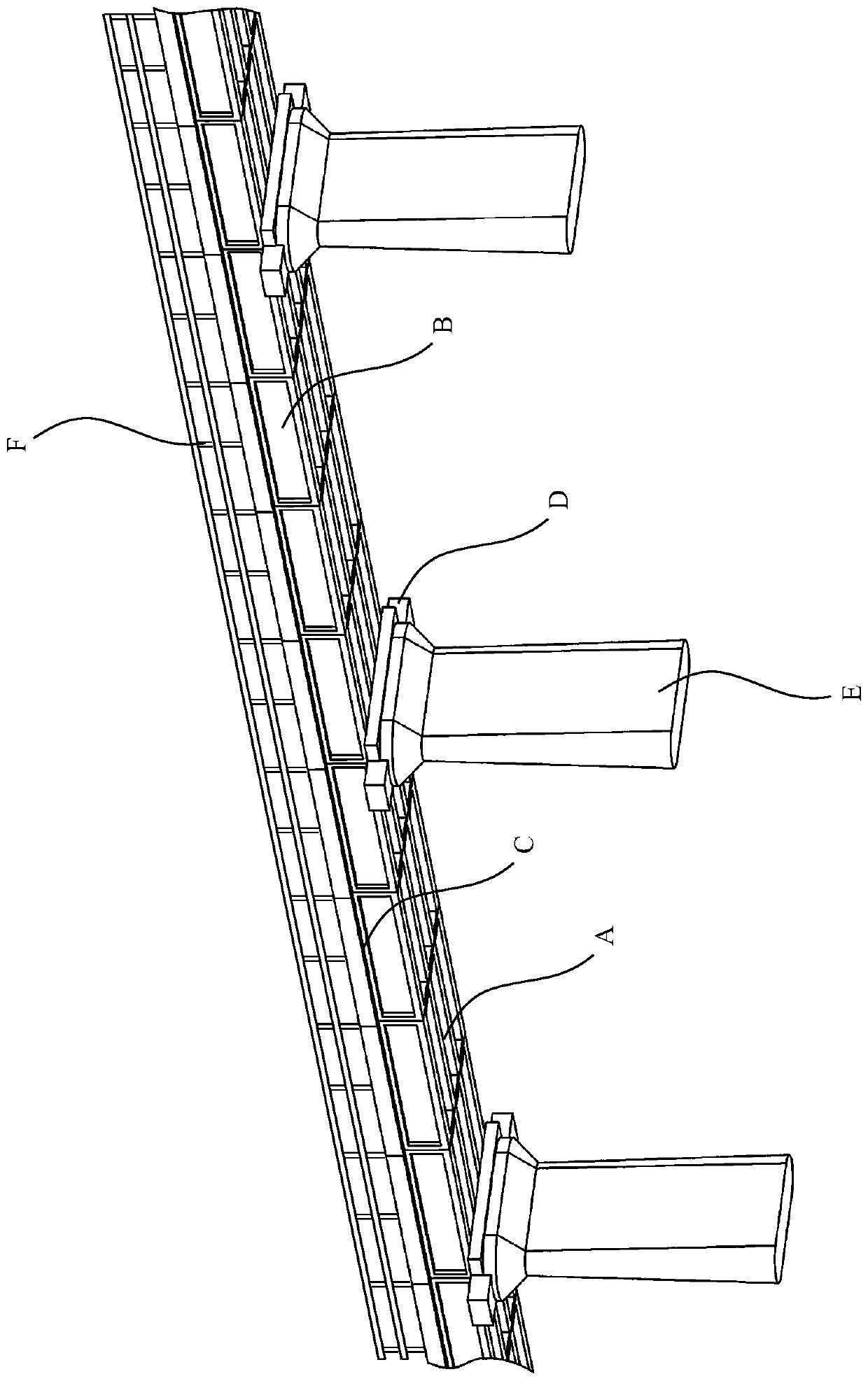
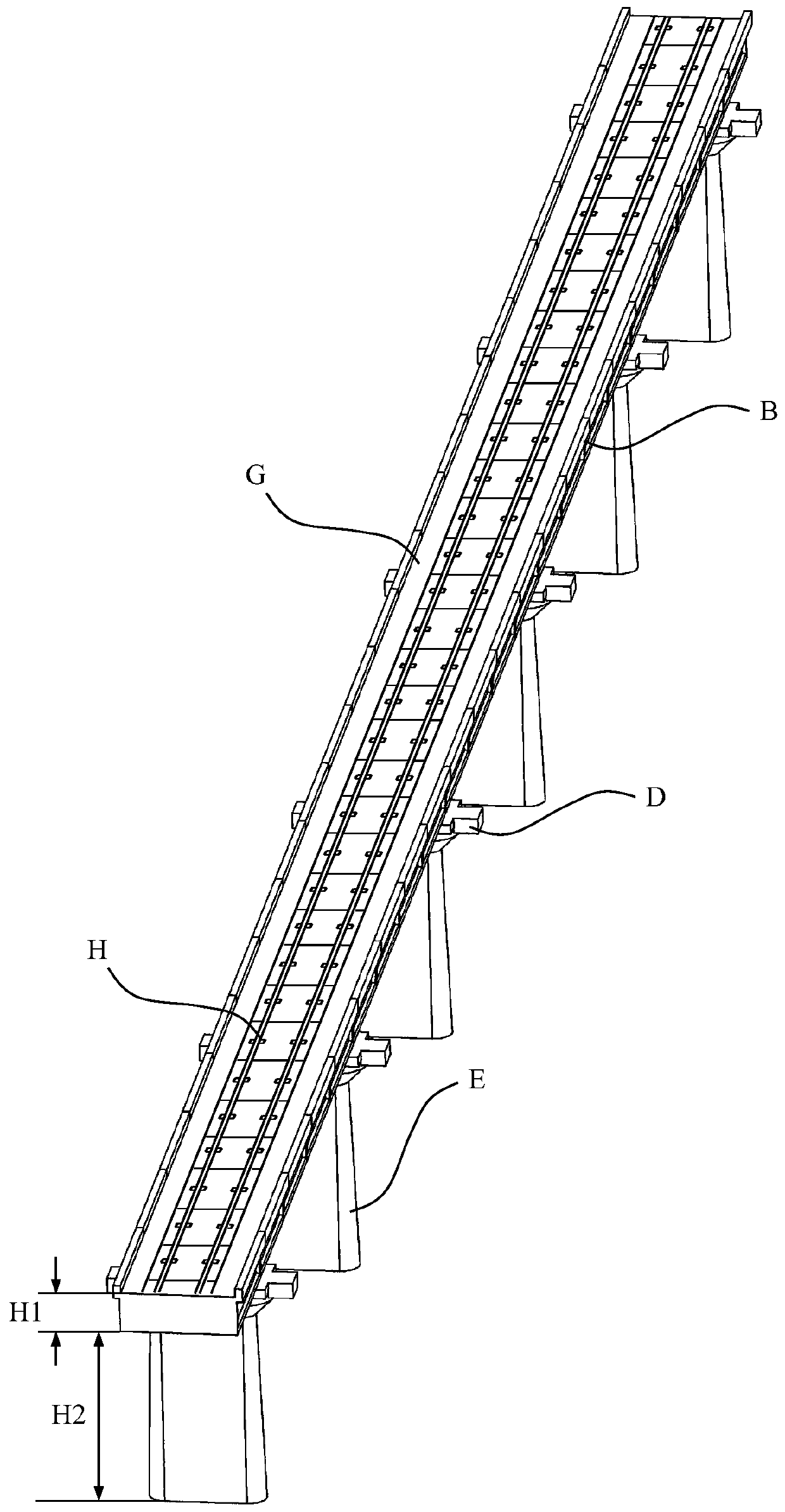
[0097] In the inspection route planning (calibration) process, firstly carry out three-dimensional measurement and modeling for the bridges that need to be inspected, and generate a three-dimensional map of the bridge; then, manually operate the UAV 10 pairs of bridge bottom, outer edge, si...

Embodiment 2

[0171] as attached Figure 5 As shown, an embodiment of a bridge inspection system based on the method described in the embodiment specifically includes: an unmanned aerial vehicle system 1 and a ground terminal system 2 . The unmanned aerial vehicle system 1 further includes an unmanned aerial vehicle 10, and an airborne data processing unit 11, a pan-tilt camera 12, a flight control module 16, an obstacle avoidance module 110 and a positioning module 111 mounted on the unmanned aerial vehicle 10, and the ground terminal system 2 further comprises a ground station 20. The UAV 10 performs the first inspection operation on the bridge to be detected under manual operation, and collects bridge surface data through the pan-tilt camera 12, and according to the positioning signal obtained by the positioning module 111 (such as: using GNSS signals, Global Navigation Satellite System , the abbreviation of global navigation satellite system, such as GPS, Glonass, Galileo, Beidou satel...

Embodiment 3

[0185] An embodiment of a bridge inspection unmanned aerial vehicle system applied to the method described in embodiment 1, specifically comprising: an unmanned aerial vehicle 10, and an airborne data processing unit 11 and a pan-tilt camera 12 mounted on the unmanned aerial vehicle 10 , the first data transmission station 13 and the first image transmission station 14. During the automatic inspection operation, the airborne data processing unit 11 sends bridge surface data acquisition control signals to the pan-tilt camera 12 , and the airborne data processing unit 11 sends flight control signals to the UAV 10 . The PTZ camera 12 acquires high-definition data on the surface of the bridge, and the bridge video data collected by the PTZ camera 12 is sent to the first image transmission station 14 through the on-board data processing unit 11, and the bridge video data is sent to the ground by the first image transmission station 14 The end system 2 performs display monitoring. ...


PUM


Abstract

The invention discloses a bridge inspection method comprising the following steps: S10, establishing a three-dimensional map of a detected bridge; S20, erecting a base station and controlling an unmanned aerial vehicle manually to plan corresponding inspection routes for all parts of the detected bridge; S30, after completion of inspection route planning of all parts of the detected bridge, loading a corresponding inspection route for a flight control module to control the unmanned aerial vehicle to carry out automatic inspection; S40, collecting, processing, and managing data sent by the unmanned aerial vehicle in an automatic inspection working process by a ground station and detecting defects existing in the detected bridge; and S50, locating the defects existing in the detected bridgeaccording to the data received by the ground station in the automatic inspection working process of the unmanned aerial vehicle. Therefore, technical problems that the automation degree is low, the workload is large, the stability of the acquired data is poor, and the safety is low because the existing UAV bridge inspection mode mainly relies on the manual operation for bridge surface data collection by the UAV are solved.

Description

technical field [0001] The invention relates to the technical field of engineering detection, in particular to a method for realizing inspection of bridges such as railways and highways by using an unmanned aerial vehicle. Background technique [0002] By the end of 2017, the national railway operating mileage reached 127,000 kilometers, including 25,000 kilometers of high-speed railways. If calculated based on the proportion of bridges accounting for 52% of the lines, there are about 10,000 kilometers of high-speed railway bridges in my country. For example, the accumulative length of the Beijing-Tianjin intercity bridge accounts for 86.6% of the total length of the main line, the Beijing-Shanghai high-speed railway accounts for 80.5%, the Guangzhou-Zhuhai intercity bridge accounts for 94.0%, the Wuhan-Guangzhou Railway Express accounted for 48.5%, and the Harbin-Dalian Railway Express accounted for 74.3%. As a routine operation type in the engineering field, bridge inspect...

Claims


Application Information

Patent Timeline
Patent Type & Authority Applications(China)
IPC IPC(8): G05D1/10G01N21/95
Inventor 颜琼李华伟王文昆罗梓河王贤朱义明廖时才
Owner ZHUZHOU TIMES ELECTRONICS TECH CO LTD
Why Eureka
Try Eureka