
A depth image restoration method for a depth camera

A depth camera, depth image technology, applied in the field of image processing, can solve problems such as unfavorable experiments, feature matching errors, reflected light, blur, etc., to achieve the effect of solving boundary misalignment, solving edge blurring, and reducing scanning time

Active Publication Date: 2019-06-18
JIANGSU UNIV
View PDF2 Cites 5 Cited by
  • Summary
  • Abstract
  • Description
  • Claims
  • Application Information

AI Technical Summary

Problems solved by technology

[0003] However, due to this imaging principle, due to feature matching errors or reflected light being absorbed, the depth image usually has holes or blurred depth edges, which is not conducive to subsequent experiments, so the depth image needs to be repaired first.
So far, many researchers have studied the restoration technology of depth images. For depth edge blurring, some researchers have proposed to use boundary-preserving filtering technology to improve depth images, and some scholars have proposed using depth image based Sampling repair algorithms, however, cannot effectively repair the specific errors of Realsense; for the hole phenomenon in depth images, some researchers have proposed to use inter-frame motion compensation and median filtering to fill black holes, but they do not consider boundary alignment and When a large-area hole is encountered, the depth value repair error will appear. Some researchers have proposed an improved fast-moving method, using color images as guiding information to fill the hole, but this method also cannot eliminate the interference around the boundary. Depth value, and there are artifacts on the edge of the repaired object

Method used


Image

  • A depth image restoration method for a depth camera
  • A depth image restoration method for a depth camera
  • A depth image restoration method for a depth camera

Examples


Embodiment Construction

[0034] The following will clearly and completely describe the technical solutions in the embodiments of the present invention with reference to the drawings in the embodiments of the present invention.

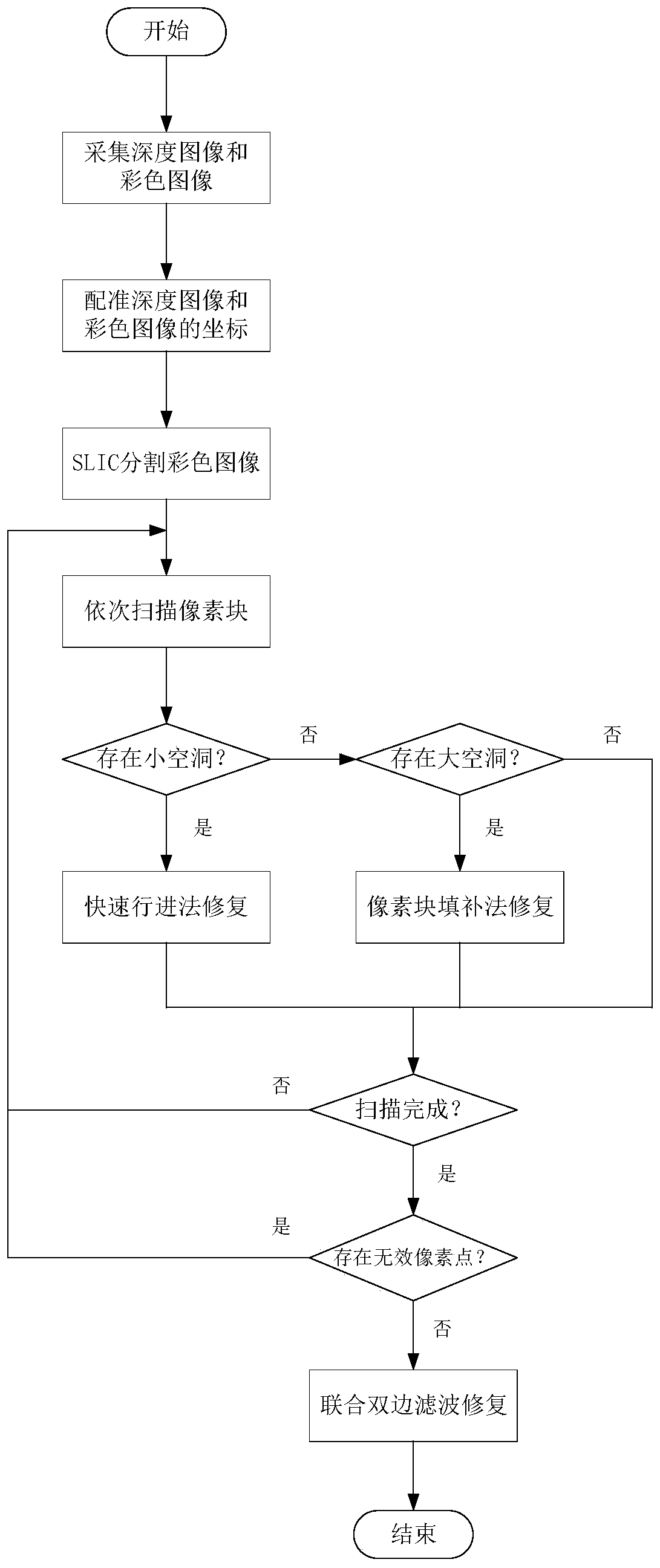
[0035] figure 1 It is a flow chart of depth image repair, in which SLIC superpixels are used to segment color images, and the coordinates corresponding to each superpixel block are mapped to the depth image; small holes are repaired by fast marching method, and large holes are repaired by similarity in adjacent pixel blocks. Texture blocks are repaired; edge blur and boundary misalignment problems are repaired by joint bilateral filtering.

[0036] Step 1: Collect the depth image and color image in the target scene in real time through the Realsense depth camera.

[0037] Step 2: Register the coordinates of the depth image and the color image.

[0038] Step 3: Divide the color image pixels into pixel blocks through the SLIC superpixel segmentation algorithm, and map the pix...


PUM


Abstract

The invention provides a depth image restoration method for a depth camera. The method comprises the following steps: firstly, registering a collected depth image and a color image; dividing Pixel points of the color image into pixel blocks through an SLIC superpixel segmentation algorithm; sequentially scanning each pixel block in the depth image; if a small hole exists in the pixel block, repairing by adopting a rapid advancing method; if a large cavity exists in the pixel block, selecting an adjacent similar pixel block, judging whether the adjacent similar pixel block and the to-be-repaired superpixel block are the same foreground or background, selecting a texture block with the highest similarity to fill and repair the to-be-repaired superpixel block, and if no effective pixel valueexists in the pixel block adjacent to the large cavity, temporarily stopping repairing the to-be-repaired superpixel block; checking whether invalid pixel points still exist in the depth image or not,if yes, finishing repairing all the pixel points, and if not, repairing each pixel block with the large cavity by adopting united bilateral filtering in combination with the color image. The method can improve the repair speed while ensuring the repair effect.

Description

technical field [0001] The invention relates to an algorithm suitable for repairing hollow points in a depth image of a Realsense depth camera, and belongs to the technical field of image processing. Background technique [0002] The Realsense depth camera was launched by Intel Corporation at the 2014 International Consumer Electronics Show, dedicated to human-computer interaction technology. It is the world's first device that integrates a 3D depth module and a 2D lens module, giving the device a similar the depth of vision of the human eye. The present invention uses the Realsense d435 depth camera, and its depth image imaging principle is the principle of structured light. The depth sensor captures the changes of the infrared signal on the surface of the object to calculate the depth value. It is widely used because it is less affected by light and has high cost performance. . [0003] However, due to this imaging principle, due to feature matching errors or reflected l...

Claims


Application Information

Patent Timeline
Patent Type & Authority Applications(China)
IPC IPC(8): G06T7/55G06T7/30G06T7/12G06T7/11G06T7/194
CPCY02A90/30
Inventor 刘慧朱晟辉沈跃
Owner JIANGSU UNIV
Learn More