Self-service retail device with pulley mechanism
A pulley and equipment technology, applied in the field of automation, can solve the problems such as the inability to meet the accurate positioning requirements of large-sized freezer items, the many fault points of the wheel-axle cable mechanism, the complex structure of the three-axis machine and the suction cup, etc., so as to save the overall development cost and extend the The longest contact distance and the effect of shortening the development cycle
- Summary
- Abstract
- Description
- Claims
- Application Information
AI Technical Summary
Problems solved by technology
Method used
Image
Examples
specific Embodiment approach
[0031] Under normal circumstances, if you use a traditional vending machine, you can only sell products stored in refrigeration (2-8°C) or at room temperature. The insulation layer of the equipment itself is very thin, and the leakage of the equipment is relatively large. The new retail automatic vending equipment of information technology doubles the moving distance of the z-axis vacuum suction cup, shortens the length of the z-axis, realizes the automatic vending and storage of frozen products, and achieves the goals of low cost, simple structure and low maintenance cost. The specific implementation is as follows:
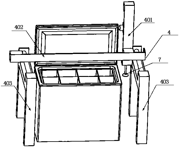
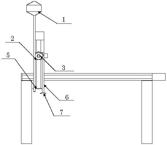
[0032] refer to figure 1 , figure 2 , a self-service retail device with a pulley mechanism, which includes a housing and a refrigerator installed in the housing, a three-axis motion mechanism 4, a pulley 3, and a suction cup 7; the three-axis motion mechanism 4 includes a Z-axis bracket 401, an X-axis Support 402, Y-axis support 403; The Y-axis support 403 in...
Embodiment 1
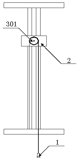
[0036] refer to image 3 , The first pulley 301 is installed on the slider 2, and the first pulley 301 on the Z axis of the three-axis motion mechanism can be installed on the left side, the front, the rear, the top, the bottom or the right side of the slider. The slider 2 can drive the first pulley 301 to move; the first pulley 301 is wound with a rope, one end of the rope is fixed on the Z axis, and one end of the rope on the pulley 3 can be fixed on the upper, middle, lower part of the Z axis or other relatively static Location. The other end is connected to the vacuum suction cup after bypassing the first pulley 301; the slider drives the pulley to move up and down, so that the rope on the pulley drives the suction cup 7 to move up and down.
Embodiment 2
[0038] The pulley 3 also includes a second pulley 302 installed on the Z axis and connected with the first pulley 301 by a rope; when the Z-axis slider moves up and down, the first pulley 301 is driven to move up and down, and the second pulley 302 is driven to rotate at the same time , thus driving the vacuum suction cup to move up and down.
[0039] It should be noted that the number of pulleys can be set as n according to the needs, so as to meet the design needs of different strokes.
PUM
 Abstract
Description
Claims
Application Information
 - R&D
- Intellectual Property
- Life Sciences
- Materials
- Tech Scout
- Unparalleled Data Quality
- Higher Quality Content
- 60% Fewer Hallucinations
Browse by: Latest US Patents, China's latest patents, Technical Efficacy Thesaurus, Application Domain, Technology Topic, Popular Technical Reports.
© 2025 PatSnap. All rights reserved.Legal|Privacy policy|Modern Slavery Act Transparency Statement|Sitemap|About US| Contact US: help@patsnap.com


