
Metal injection molding (MIM) linear type automatic sand blasting machine

A sandblasting machine, linear technology, applied in the direction of abrasive jetting machine tools, used abrasive processing devices, abrasives, etc., can solve the problems of unstable sandblasting effect, difficult continuous sandblasting operation, unsafe operation, etc. Achieve the effect of reducing the secondary sand removal process, improving production capacity and efficiency, and improving production efficiency

Pending Publication Date: 2019-06-21
DONGGUAN HUAJING POWDER METALLURGY
View PDF0 Cites 0 Cited by
  • Summary
  • Abstract
  • Description
  • Claims
  • Application Information

AI Technical Summary

Problems solved by technology

[0003] The surface of the injection-molded product often has problems such as edging, which not only affects the appearance of the product, but also easily affects the assembly and use of the product. Therefore, the molded product often needs to be polished by sandblasting equipment Most of the existing sandblasting equipment is manual sandblasting. During operation, it is necessary to manually put the product into the machine cavity and close the side door panel; then reach into the machine and hold the sandblasting gun to align the product Sandblasting operation, this operation method requires high requirements for personnel's operating experience, large demand for personnel, and the sandblasting effect is unstable, the operation is unsafe, and it is difficult to achieve continuous sandblasting operation, low production capacity, low efficiency, and high production costs

Method used


Image

  • Metal injection molding (MIM) linear type automatic sand blasting machine
  • Metal injection molding (MIM) linear type automatic sand blasting machine
  • Metal injection molding (MIM) linear type automatic sand blasting machine

Examples


Embodiment Construction

[0035] The technical solutions of the present invention will be further described below in conjunction with the accompanying drawings and through specific implementation methods.

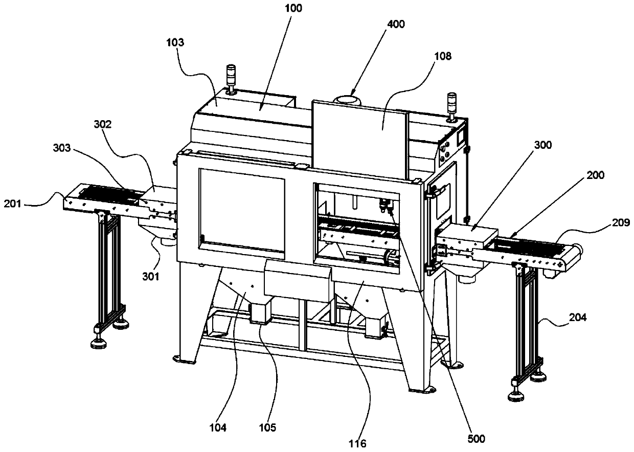
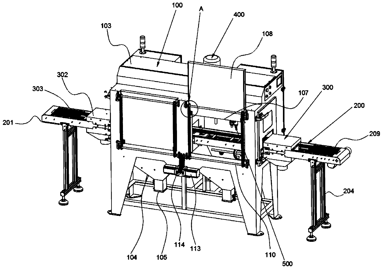
[0036] Such as figure 1 , figure 2 as well as Figure 5 As shown, it includes a main chassis 100, at least one sandblasting chamber 102 located in the main chassis 100, a swing sandblasting device 500 correspondingly fixed in the sandblasting chamber 102, penetrating the main chassis 100 and the sandblasting chamber 102 in the lateral direction The chain conveying device 200, the dust extraction device 400 communicated with the sandblasting chamber 102, and the sandblasting inlet position and the sandblasting inlet position near the sandblasting chamber 102 are respectively located on the chain conveying device 200 and located on the side of the main chassis 100. The air washing device 300 located at the other side of the main chassis 100 near the sandblasting outlet of the sandblasting chamber 1...


PUM


Abstract

The invention discloses a metal injection molding (MIM) linear type automatic sand blasting machine, and belongs to the technical field of sand blasting equipment. The MIM linear type automatic sand blasting machine comprises a main case, at least one sand blasting chamber located in the main case, a swinging sand blasting device correspondingly arranged in the sand blasting chamber, a chain typeconveying device penetrating through the main case and the sand blasting chamber in the horizontal direction, a dust exhaust device communicating with the sand blasting chamber, and air purging devices erected on the chain type conveying device and located on two sides of the main case. Each air purging device comprises a lower tank fixed to the bottom part of a rack of the chain type conveying device, an upper tank fixed to the top part of the rack of the chain type conveying device and fits to the lower tank in a covering way, multiple air delivery pipes fixed into the upper tank, and an airdelivery pump communicating with the air delivery pipes; multiple air injection holes distributed along the length directions of the air delivery pipes and arranged downwards vertically are formed inthe bottom part of the air delivery pipes; and air purging areas are formed between the air delivery pipes and a conveying chain of the chain type conveying device. Continuous sand blasting operationis realized, the production efficiency is improved, and a follow-up secondary desanding process is reduced.

Description

technical field [0001] The invention relates to the technical field of sandblasting equipment, and more specifically, relates to a MIM linear automatic sandblasting machine. Background technique [0002] Metal (ceramic) powder injection molding technology (Metal Injection Molding, referred to as MIM technology) is the product of the interpenetration and intersection of plastic molding technology, polymer chemistry, powder metallurgy technology and metal materials. Forming blanks and quickly manufacturing high-density, high-precision, three-dimensional complex structural parts through sintering can quickly and accurately materialize design ideas into products with certain structural and functional characteristics and directly mass-produce parts. It is a manufacturing technology industry. A new revolution. [0003] The surface of the injection-molded product often has problems such as edging, which not only affects the appearance of the product, but also easily affects the as...

Claims


Application Information

Patent Timeline
IPC IPC(8): B24C3/02B24C9/00
Inventor 邓声志
Owner DONGGUAN HUAJING POWDER METALLURGY
Features
  • Generate Ideas
  • Intellectual Property
  • Life Sciences
  • Materials
  • Tech Scout
  • Unparalleled Data Quality
  • Higher Quality Content
  • 60% Fewer Hallucinations
Learn More