Waste plastic recycling equipment

A waste plastic recycling technology, applied in the direction of plastic recycling, recycling technology, mechanical material recycling, etc., can solve the problems of bubbles and cracks in plastic products, achieve full contact, high efficiency, and reduce water content.

Inactive Publication Date: 2019-06-21
浙江安尚电气有限公司
View PDF10 Cites 1 Cited by
  • Summary
  • Abstract
  • Description
  • Claims
  • Application Information

AI Technical Summary

Problems solved by technology

[0002] The recycling of waste plastics can not only greatly save resources, but also reduce environmental pollution and improve the quality of the ecological environment. It is an important measure for the development of resources; the traditional process is to crush and clean the recycled waste plastics, Then granulation is carried out by screw extrusion, resulting in the reuse of waste plastics containing a lot of water. If the water cannot be removed before granulation, the plastic granules produced will contain a lot of water. These plastic granules containing water will be heated and plasticized A large amount of water vapor will be generated during the process, and the water vapor will cause bubbles and cracks in the molded plastic products

Method used


Image

  • Waste plastic recycling equipment
  • Waste plastic recycling equipment
  • Waste plastic recycling equipment

Examples


Embodiment 1

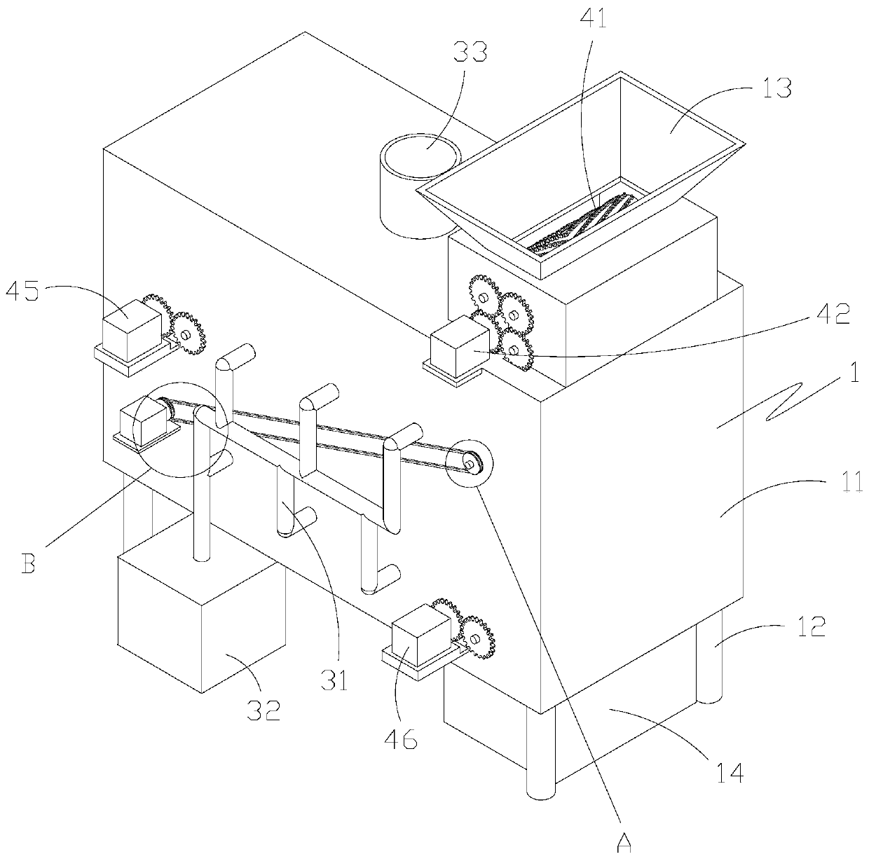
[0026] like Figure 1-8 As shown, a waste plastic recycling equipment includes a casing 1, a drying device and a crushing device; the casing 1 includes a casing 11, a support column 12, a feed hopper 13 and a collecting hopper 14; the support column is welded to the casing On the lower surface of the shell, it plays the role of supporting and fixing the shell; on the upper surface of the shell, a feeding hopper is installed to facilitate adding raw materials into the shell; a collecting hopper is placed under the shell, so that from the shell The finished material discharged from the discharge port can be collected by the collecting hopper, which is convenient for subsequent processing.

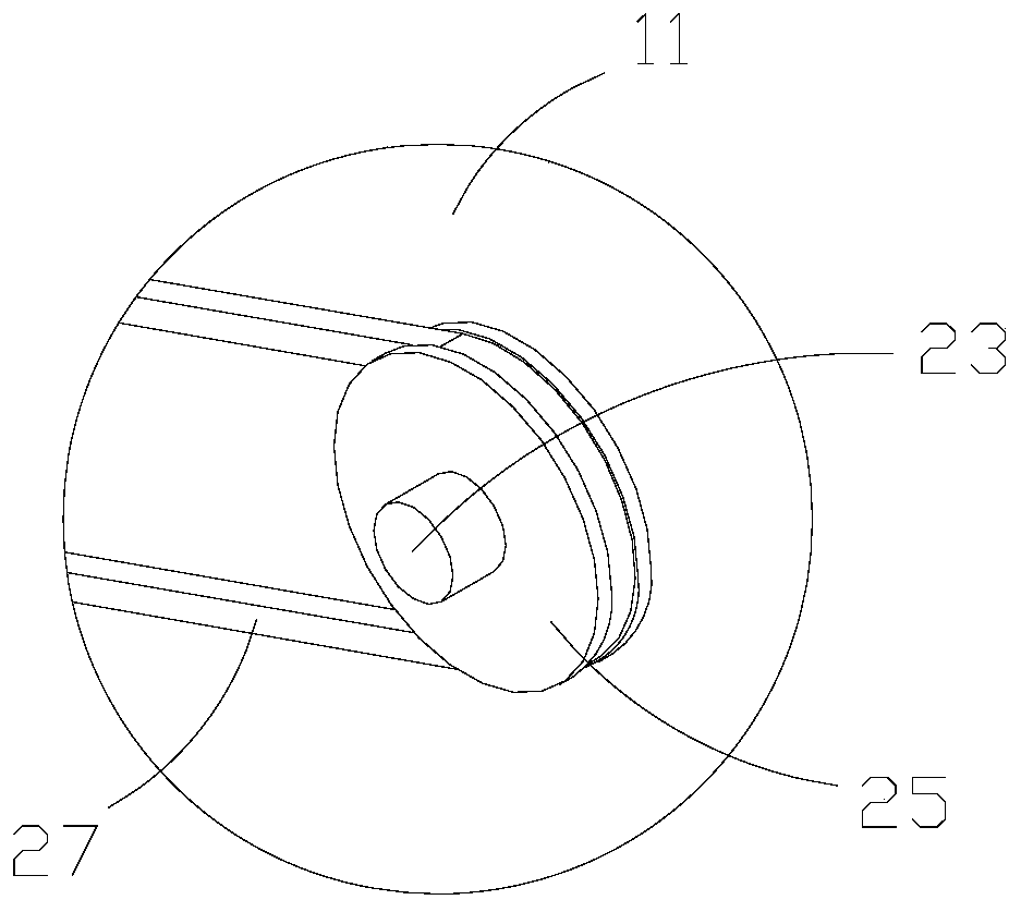
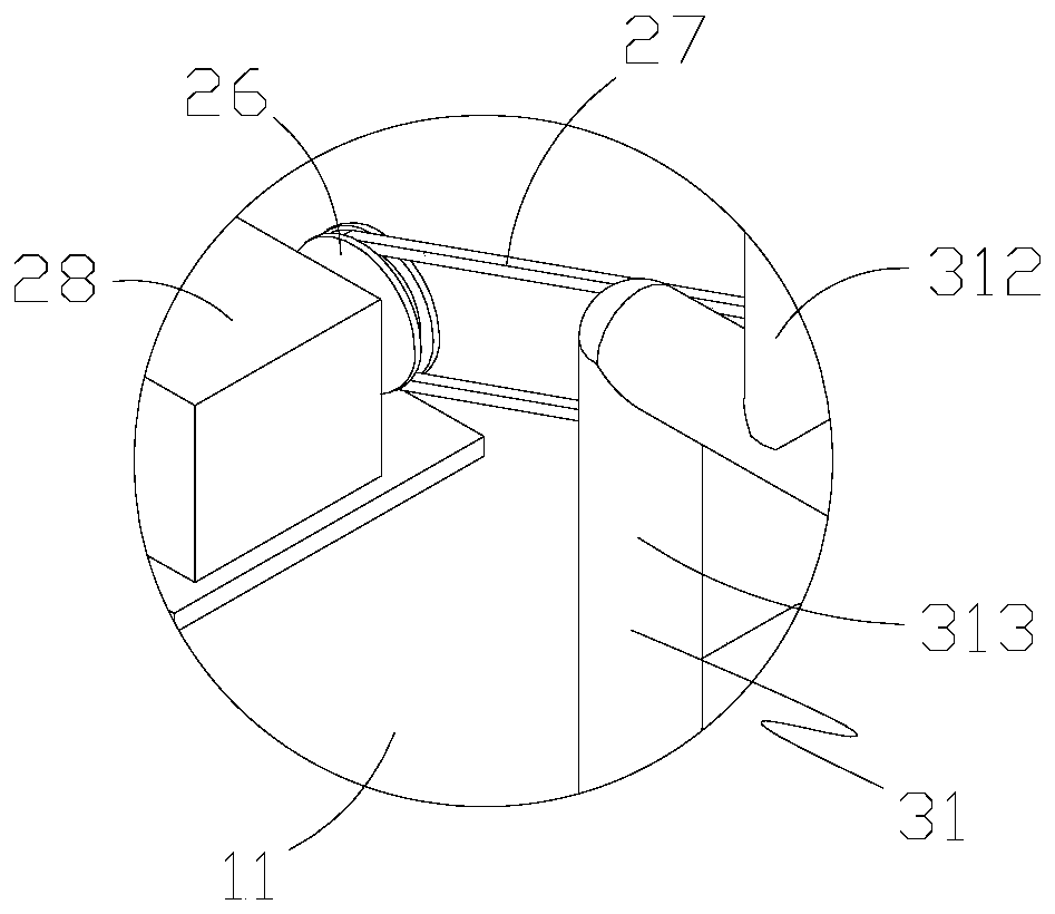
[0027] Specifically, the drying device includes an air outlet structure, a vibrating structure and a vibrating driving structure; wherein the vibrating structure includes an upper vibrating plate 20, a lower vibrating plate 21 and a material blocking plate 22; both the upper vibrating plate a...

Embodiment 2

[0034] like Figure 9-10 As shown, the difference between this embodiment and Embodiment 1 is that the crushing device is optimized. The crushing device includes a primary crushing roller set, a first power member 42, a primary transmission structure and a secondary crushing structure. The primary crushing roller set is installed in the Inside the hopper 13, it includes a first roller 411, a second roller 412, a third roller 413 and a fourth roller 414; wherein the first roller 411 includes a roller shaft 4111, a front crushing belt 4112 and a rear crushing belt 4113, the two ends of the roller shaft are respectively connected with the inner wall bearing of the feeding hopper, so that the first roller can rotate back and forth relative to the feeding hopper; the front crushing belt and the rear crushing belt are installed on the outer surface of the roller shaft, It is distributed in a spiral structure, and multiple front crushing zones and rear crushing zones are uniformly op...


PUM


Abstract

The invention discloses waste plastic recycling equipment which comprises a machine shell, a drying device and a crushing device, wherein the drying device is arranged in the machine shell, and the crushing device is matched with the drying device. The drying device comprises an air outlet structure capable of providing hot air, a vibration structure for enabling plastic to be in full contact withhot air and a vibration driving structure matched with the vibration structure, wherein the vibration structure comprises an upper vibrating plate capable of moving back and forth, a lower vibratingplate capable of moving back and forth, and material blocking plates matched with the upper vibrating plate and the lower vibrating plate. The water content of the plastic is reduced through the arrangement of the drying device, so that bubbles or cracking of plastic products is avoided, the rate of finished products is improved, and the rejection cost is reduced; through the arrangement of the upper vibrating plate and the lower vibrating plate, the drying effect is better, and drying is more efficient.

Description

technical field [0001] The invention belongs to the technical field of plastic production equipment, and in particular relates to recycling and reuse equipment for waste plastics. Background technique [0002] The recycling of waste plastics can not only greatly save resources, but also reduce environmental pollution and improve the quality of the ecological environment. It is an important measure for the development of resources; the traditional process is to crush and clean the recycled waste plastics, Then granulation is carried out by screw extrusion, resulting in the reuse of waste plastics containing a lot of water. If the water cannot be removed before granulation, the plastic granules produced will contain a lot of water. These plastic granules containing water will be heated and plasticized A large amount of water vapor will be generated during the process, and the water vapor will cause bubbles and cracks in the molded plastic products. Contents of the invention ...

Claims


Application Information

Patent Timeline
Patent Type & Authority Applications(China)
IPC IPC(8): B29B17/00B29B17/04
CPCY02W30/52Y02W30/62
Inventor 金志远
Owner 浙江安尚电气有限公司
Why Eureka
Try Eureka