Foundation pit supporting composite retaining wall and construction method thereof

A composite retaining wall and foundation pit support technology, which can be used in infrastructure engineering, excavation, artificial islands, etc., can solve the problems of reducing cost reduction, reducing the requirements of insertion accuracy, and long construction period of concrete piles.

Inactive Publication Date: 2019-06-21
刘小檀 +1
View PDF0 Cites 3 Cited by
  • Summary
  • Abstract
  • Description
  • Claims
  • Application Information

AI Technical Summary

Problems solved by technology

Although this kind of retaining wall reduces the number of piles and reduces the reduction compared with the double-row pile retaining wall; compared with the plug-in sheet pile retaining wall, it reduces the requirements for insertion accuracy, and Water-stop components can also be recycled and reused, but the construction period of concrete piles is long, and the number of concrete piles that play the main role of retaining soil is large, resulting in relatively high costs

Method used


Image

  • Foundation pit supporting composite retaining wall and construction method thereof
  • Foundation pit supporting composite retaining wall and construction method thereof
  • Foundation pit supporting composite retaining wall and construction method thereof

Examples


Embodiment 1

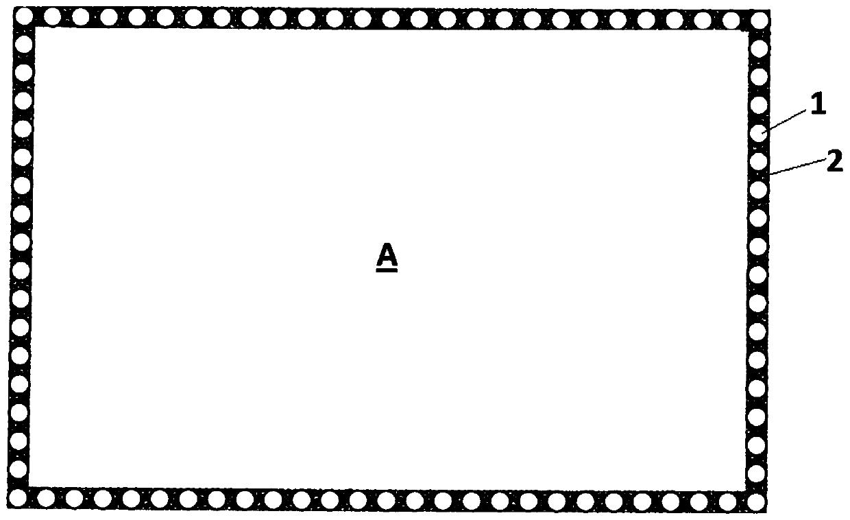
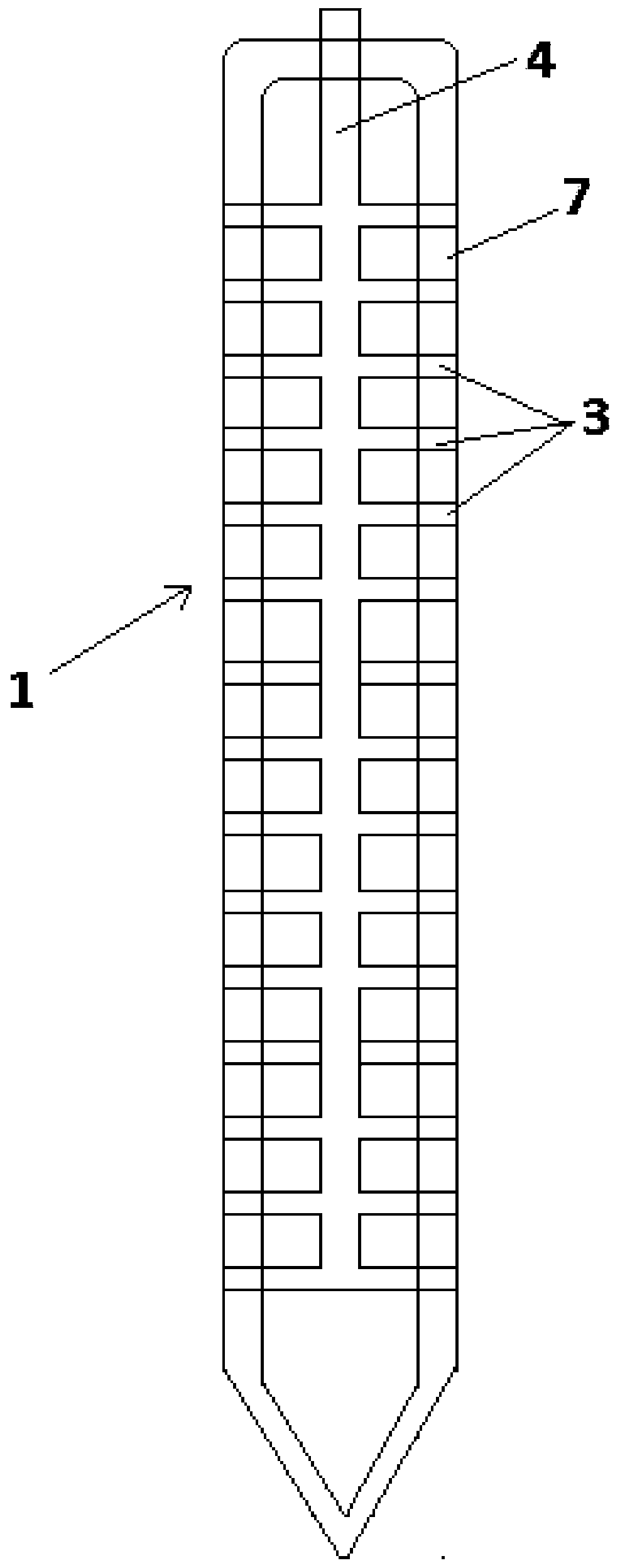
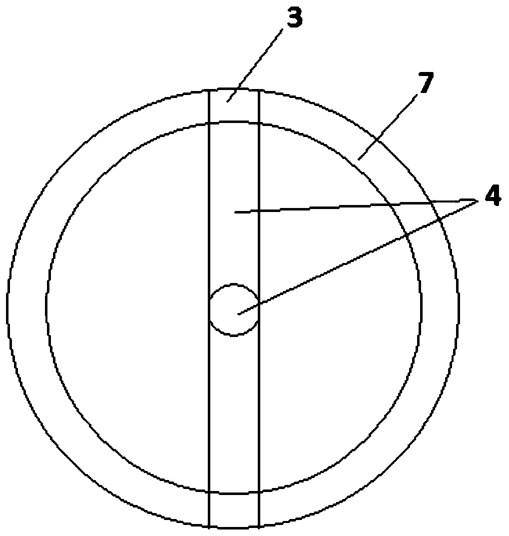
[0033] Such as figure 1 As shown, a foundation pit support composite retaining wall provided by the embodiment of the invention includes: several pipe piles 1 arranged in the circumferential direction; cement-soil retaining wall part 2, located between two adjacent pipe piles, and It is connected with the pipe pile to form a circumferentially closed retaining wall; the foundation pit A is formed inside the composite retaining wall, wherein, as figure 2 and image 3 As shown, the pipe wall 7 of the pipe pile 1 is provided with a grouting structure corresponding to the cement-soil retaining wall part. As an optional embodiment, the pipe pile can be a hollow structure with an upper opening, so The grouting structure includes: a plurality of first through holes 3 formed on the pipe wall 7 of the pipe pile 1 corresponding to the portion of the cement-soil retaining wall, and communicating with the first through holes 3 The first grouting pipe 4 arranged inside the pipe pile 1; b...

Embodiment 2

[0039] The embodiment of the invention discloses a construction method for a foundation pit support composite retaining wall, such as Figure 6 and 7 As shown, it includes: a. using a piling device to insert several pipe piles into the soil at the pile positions arranged in the circumferential direction until a predetermined depth, wherein the pipe wall of the pipe pile is provided with the cement-soil retaining The grouting structure corresponding to the wall part; b. using grouting equipment to inject cement slurry 12 into the soil through the grouting structure to form a cement-soil structure connected with the pipe pile, and then cooperate with the pipe pile to form Circumferentially closed retaining wall.

[0040] As an optional embodiment, the pipe pile is a hollow structure with an upper opening; the grouting structure includes: several holes formed on the pipe wall of the pipe pile corresponding to the cement-soil retaining wall The first through hole, and the first ...


PUM


Abstract

The invention provides a foundation pit supporting composite retaining wall. The foundation pit supporting composite retaining wall comprises a plurality of pipe piles arranged in the circumferentialdirection, and a cement soil retaining wall part positioned between two adjacent pipe piles and connected with the pipe piles to form a circumferentially closed retaining wall, wherein a grouting structure corresponding to the cement soil retaining wall part is arranged on the pipe wall of the pipe pile. The foundation pit composite cement soil retaining wall is simple in structure, simple in overall construction operation, short in construction period and low in cost. The invention further provides a construction method for the foundation pit supporting composite retaining wall.

Description

technical field [0001] The invention relates to a construction method of a retaining wall in the field of foundation pit support, in particular to a foundation pit support composite retaining wall and a construction method thereof. Background technique [0002] The cement-soil retaining wall in the prior art is usually drilled into the soil body through the drill pipe and drill bit of the drilling rig, and then the cement slurry is injected into the soil body through the grouting pipe to form the cement-soil pile body; For the cement-soil pile retaining wall, the pile holes drilled by the drilling rig need to have overlapping parts. However, although the pure cement-soil occlusal pile retaining wall has good water-stop performance, its ability to retain soil is poor; The soil capacity of the concrete piles is the reason for the retaining wall. Concrete pile retaining wall has better soil retaining capacity because of its strong structure and better compressive performance....

Claims


Application Information

Patent Timeline
Patent Type & Authority Applications(China)
IPC IPC(8): E02D17/04E02D29/02E02D5/28
Inventor 刘小檀刘献刚
Owner 刘小檀
Why Eureka
Try Eureka