
Digital intelligent direct-travel electric actuator

An electric actuator, intelligent technology, applied in the direction of engine components, valve details, valve operation/release devices, etc., can solve the problems of complicated installation and debugging, unable to achieve intelligent control, easy to loose travel switch, etc., to reduce maintenance. frequency, the effect of improving the efficiency of installation and debugging

Inactive Publication Date: 2019-06-21
深圳市新可优科技有限公司
View PDF3 Cites 3 Cited by
  • Summary
  • Abstract
  • Description
  • Claims
  • Application Information

AI Technical Summary

Problems solved by technology

This structure cannot achieve intelligent control technically, which makes installation and debugging complicated and requires professional operation. It is easy to drift in the case of vibration and is not stable enough.
[0003] At present, the domestic products in the same industry mainly use ordinary motors as the power components of the actuator, but it is currently impossible to implement high-precision control technology, so the control of the valve stroke can only be achieved by using a stroke switch and a position sensor to control the valve position. , the control precision is low, and the travel switch is easy to loosen under the condition of vibration, which requires professional personnel to carry out maintenance and debugging

Method used


Image

  • Digital intelligent direct-travel electric actuator
  • Digital intelligent direct-travel electric actuator
  • Digital intelligent direct-travel electric actuator

Examples


Embodiment 1

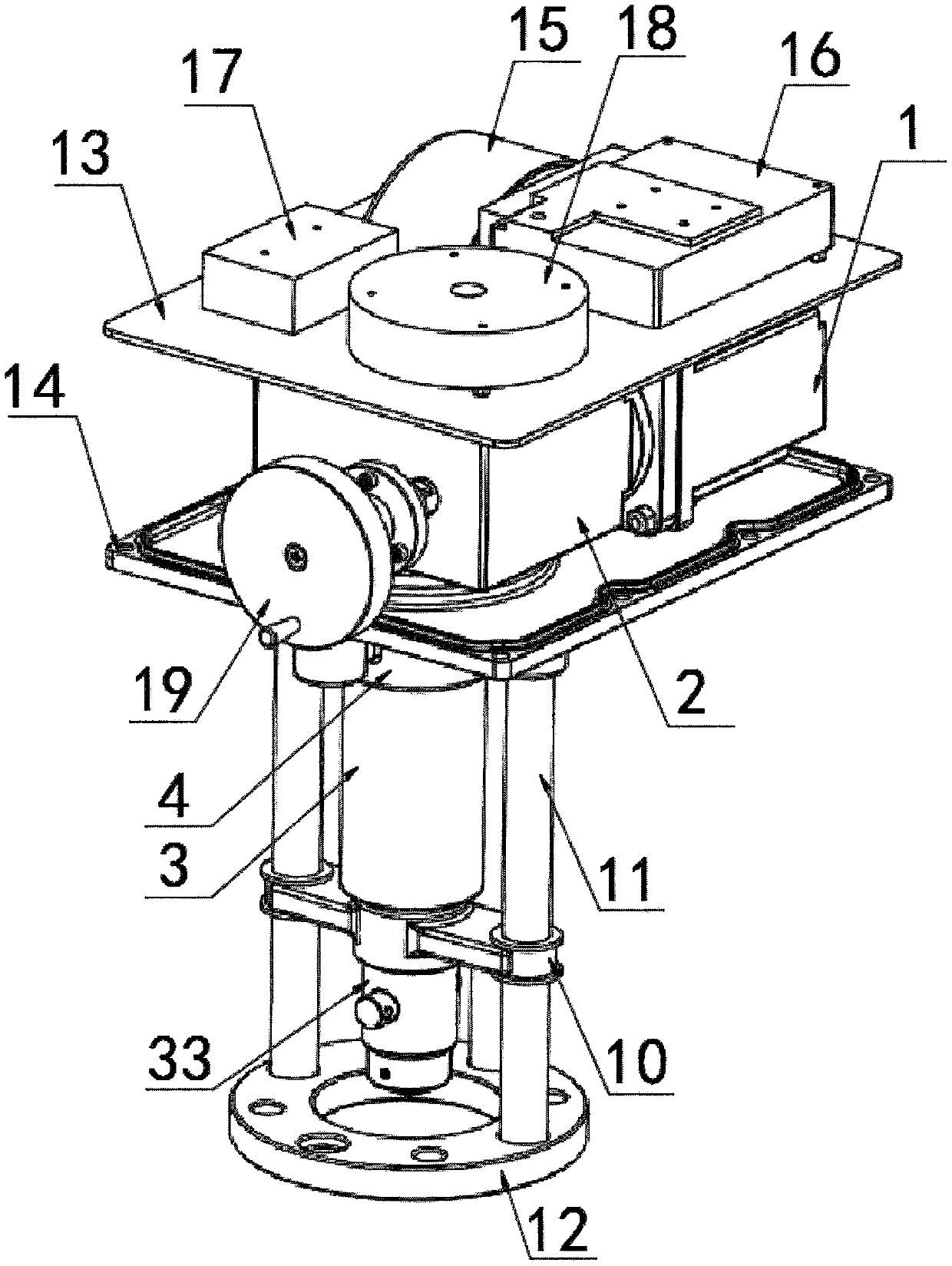
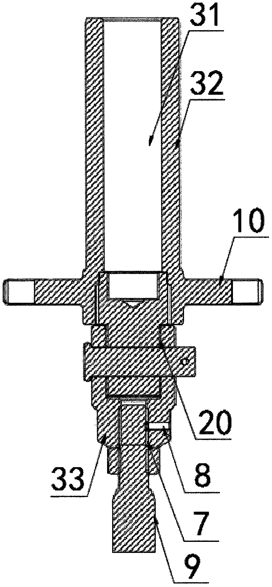
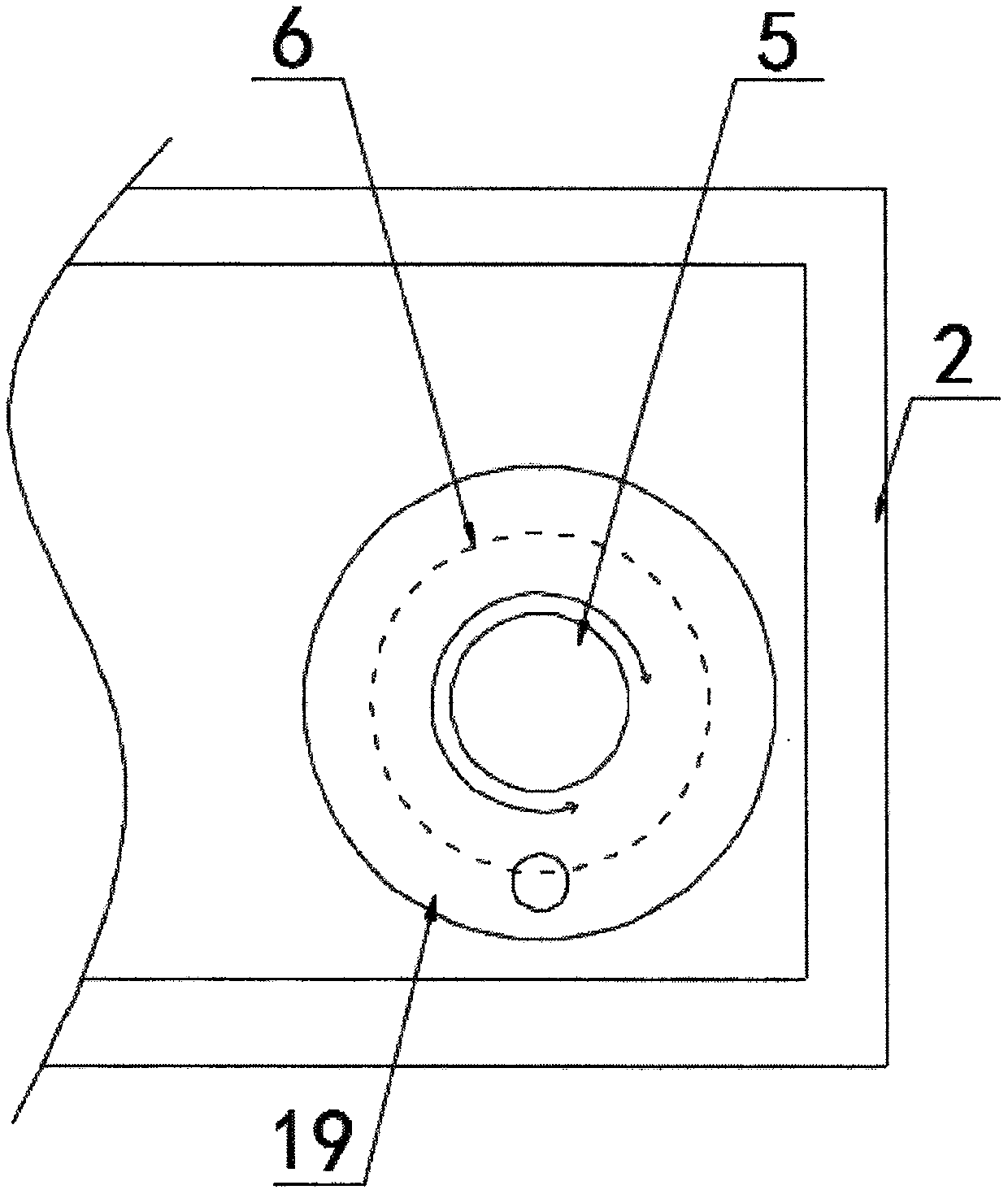
[0028] according to Figure 1-4 A digital intelligent linear electric actuator shown includes a stepper motor 1, a reducer 2 and a screw drive mechanism 3. The reducer 2 is arranged on the front side of the stepper motor 1 and connected to the stepper motor 1. Transmission connection, the screw drive mechanism 3 is arranged at the bottom of the reducer 2 and is connected with the reducer 2 through the longitudinal shaft 4. The stepping motor 1 is connected to the horizontal shaft 5, and the fixed sleeve on the horizontal shaft 5 is provided with a rotating shaft. Encoder 6, the screw drive mechanism 3 includes an inner screw rod 31 and an outer sleeve 32, the outer sleeve 32 is movably arranged outside the inner screw rod 31, and the bottom end of the inner screw rod 31 is fixed by a bracket. A joint 33, the bottom of the joint 33 is provided with a valve stem 9, the outer sleeve 32 is fixedly sleeved with a positioning bracket 10, and the two ends of the positioning bracket 1...

Embodiment 2

[0035] according to figure 1 As shown in a digital intelligent linear electric actuator, the motor drive controller 16 is set on the side of the power supply 15, the junction box 17 is set on the front side of the power supply 15, and the control module 18 is set on the motor drive The front side of the controller 16, the motor drive controller 16 is electrically connected with the stepper motor 1, the control module 18 includes a CPU, and voltage sensors, current sensors and temperature sensors are integrated on the control module 18, the control module 18 The top of the module 18 is provided with a control button;

[0036] The voltage sensor model is set to CHV-25P, the current sensor model is set to HKA-3YSD, the temperature sensor model is set to WZP-PT100, the rotary encoder 6 model is set to FCL28-R, the rotary encoder 6, voltage Sensors, current sensors and temperature sensors are connected to the CPU through the A / D converter, the CPU is connected to the stepper motor...


PUM


Abstract

The invention discloses a digital intelligent direct-travel electric actuator, and particularly relates to the field of electric actuators. The digital intelligent direct-travel electric actuator comprises a stepping motor, a speed reducer and a screw rod transmission mechanism, wherein the speed reducer is arranged on the front side of the stepping motor and is in transmission connection with thestepping motor, the screw rod transmission mechanism is arranged at the bottom of the speed reducer and is in transmission connection with the speed reducer through a longitudinal rotating shaft, andthe stepping motor is connected with a transverse rotating shaft. The stepping motor is controlled by a control module to drive the screw rod transmission mechanism to work, the intelligent control actuator enters the initialization stage, the stepping motor drives the transverse rotating shaft to rotate forwards and backwards, the stepping motor is blocked through mechanical limiting of the connected valve, a memory zero point position and a 100% point position are memorized by a CPU, the CPU is used for equally dividing according to a preset precision grade, the debugging is completed, theinstallation and debugging are simple, the zero position is not required to be adjusted frequently, the self-diagnosis can be carried out, and the maintenance frequency is reduced.

Description

technical field [0001] The invention relates to the technical field of electric actuators, and more specifically, the invention relates to a digital intelligent linear stroke electric actuator. Background technique [0002] The electric actuators currently on the market use ordinary motors as power components, potentiometers as position sensing components, and travel switches as control components for zero position and 100% position. This kind of structure cannot achieve intelligent control technically, which makes installation and debugging complicated and requires professional operation. It is easy to drift under the condition of vibration and is not stable enough. [0003] At present, the domestic products in the same industry mainly use ordinary motors as the power components of the actuator, but it is currently impossible to implement high-precision control technology, so the control of the valve stroke can only be achieved by using a stroke switch and a position sensor...

Claims


Application Information

Patent Timeline
Patent Type & Authority Applications(China)
IPC IPC(8): F16K31/04F16K31/50F16K37/00
Inventor 曹锦黄因兵沈力
Owner 深圳市新可优科技有限公司
Learn More