Heating furnace adopting biomass particles

A technology of biomass pellets and heating stoves, applied in the direction of grates, mobile grates, combustion methods, etc., can solve problems such as fire, corrosion, and increased cost of use for consumers, and achieve the effect of reducing the cost of use

Pending Publication Date: 2019-06-21
范建书
View PDF1 Cites 6 Cited by
  • Summary
  • Abstract
  • Description
  • Claims
  • Application Information

AI Technical Summary

Problems solved by technology

[0004] (1) Most of the biomass particles will coke to produce coke slag after burning, and the coking will lead to poor air intake. If the biomass particles are not fully burned, black smoke will be emitted. The substances in the black smoke are easily adsorbed on the furnace wall and smoke exhaust In the pipeline, it causes damage such as blockage and corrosion to the equipment, and the coke block blocks the ignition port, causing the stove to fail to ignite normally;
[0005] (2) During use, coking causes the biomass particles to burn untimely, but the feed rate of the biomass particles remains unchanged, making the biomass particles accumulate in the combustion box and overflow into the ash hopper continuously, resulting in In case of fire, the flame is not easy to extinguish after shutdown, and there is a potential safety hazard. In addition, if the coking time is long, the biomass particles will block the feeding channel and cause the material to be jammed, thereby introducing the fire flame into the silo, causing a safety accident;
[0006] (3) Since there are too few non-coking high-quality biomass particles on the market, and the supply is in short supply, its price co

Method used


Image

  • Heating furnace adopting biomass particles
  • Heating furnace adopting biomass particles
  • Heating furnace adopting biomass particles

Examples


Embodiment Construction

[0051] In order to make the object, technical solution and advantages of the present invention clearer, the present invention will be further described in detail below in conjunction with the accompanying drawings and embodiments. It should be understood that the specific embodiments described here are only used to explain the present invention and not to limit the present invention.

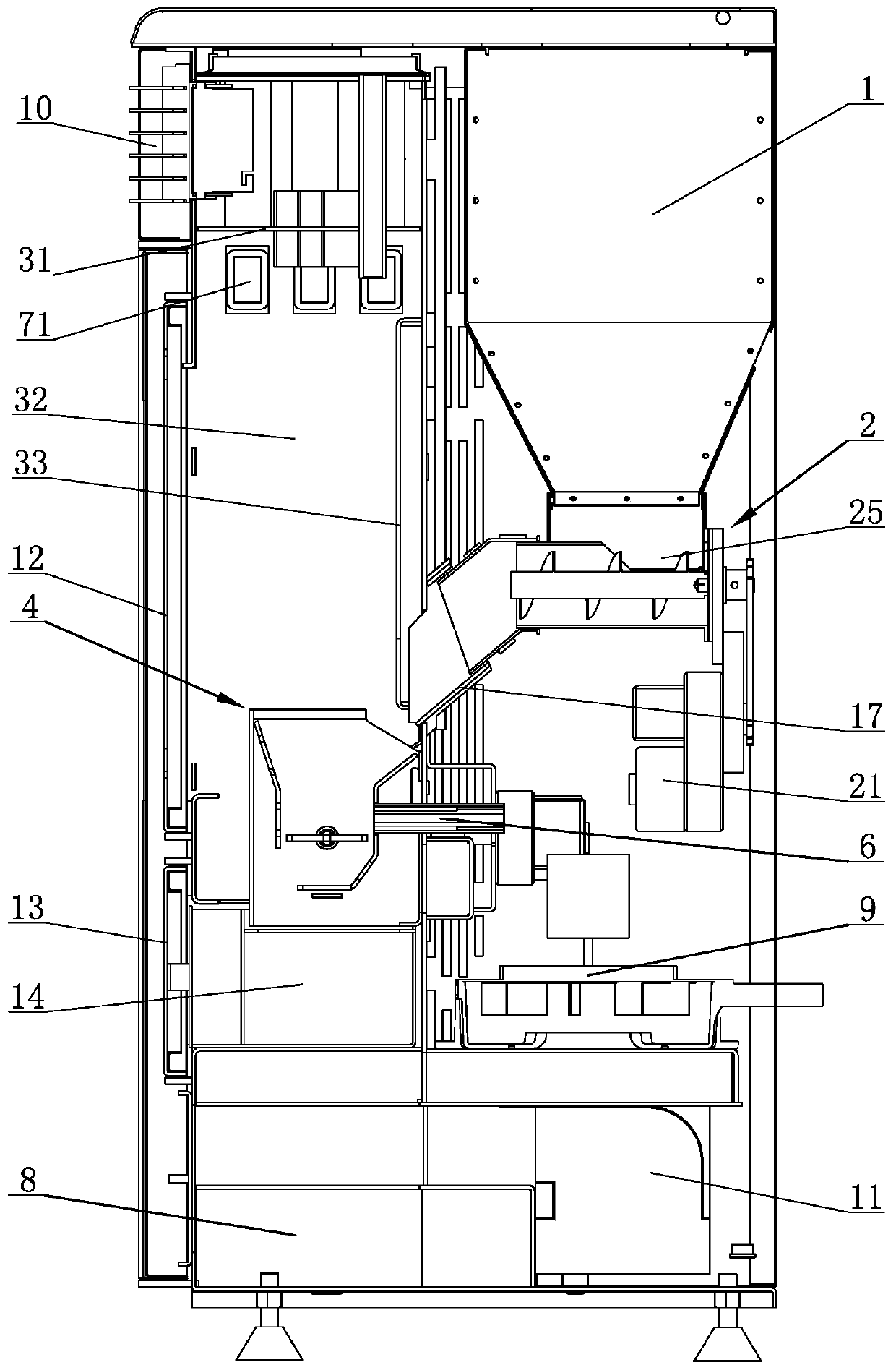
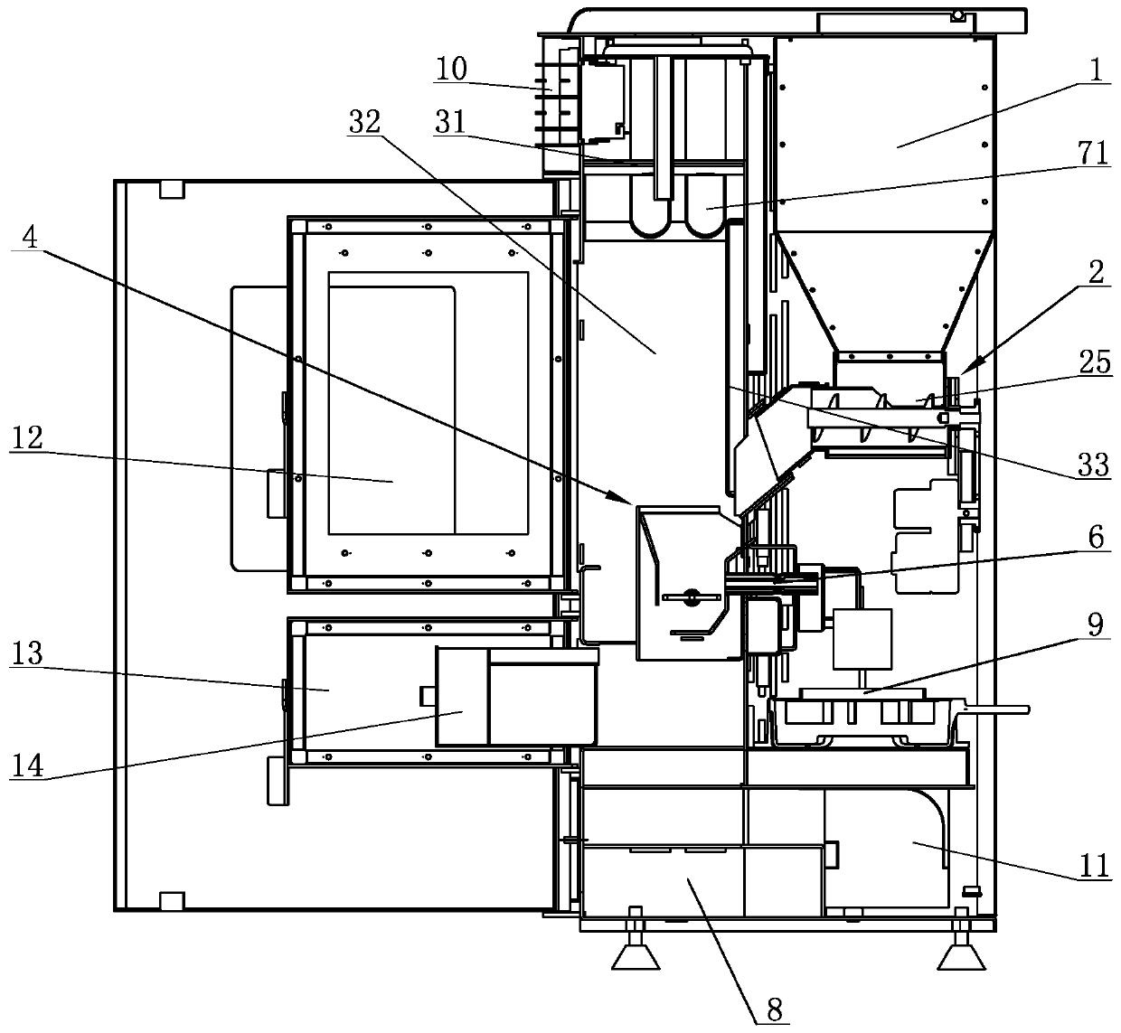
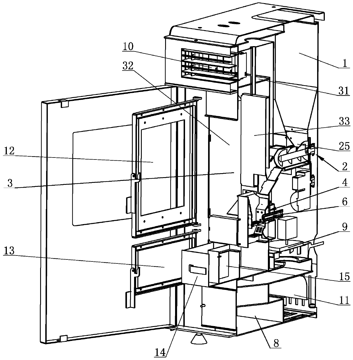
[0052] Definition: the side toward which the hot air outlet 10 of the heating furnace is directed is the front side, the side opposite to the front side is the rear side, and the rest are the upper side, the lower side, the left side and the right side.

[0053] Such as figure 1 , figure 2 , image 3 and Figure 4 Commonly shown, a biomass pellet heating furnace includes: a silo 1, a feeding device 2, a combustion chamber 3, a combustion chamber 4, an air intake device and a smoke exhaust device.

[0054] The biomass particles in the silo 1 are fed into the combustion chamber 4 by the feedi...


PUM


Abstract

The invention discloses a heating furnace adopting biomass particles. The heating furnace comprises a burning chamber, a burning container located inside the burning chamber and a feeding device for conveying materials inside a bin to the burning container; the burning container comprises a burning box; a rotating fire grate and a fixed fire grate are arranged in the burning box; the rotating firegrate is located above the fixed fire grate and is rotationally mounted in the burning box; the fixed fire grate is fixed to the burning box; and a slag discharging opening is reserved between the fixed fire grate and the burning box and is used for discharging coke slag on the fixed fire grate through rotation of the rotating fire grate. During coke cleaning, the rotating fire grate rotates by 180 degrees in the fixed direction, the coke slag on the rotating fire grate and the burning biomass particles are thoroughly overturned onto the fixed fire grate, the biomass particles are burned continuously on the fixed fire grate, the biomass particles falling onto the rotating fire grate newly are ignited, when the rotating fire grate is overturned by 180 degrees again, the coke slag is pushedout of the slag discharging opening, and the flame cannot be extinguished in the coke cleaning process, so that nonstop coke cleaning is realized, and thorough coke cleaning is achieved; and variousbiomass particles can be used by the heating furnace.

Description

technical field [0001] The invention relates to the technical field of heating furnaces, in particular to a biomass particle heating furnace. Background technique [0002] By using biomass fuel instead of coal for heating, the smoke and other harmful gases produced during the combustion of coal can be reduced, and the combustion of biomass fuel will not pollute the environment, which is more in line with the concept of environmental protection. Biomass pellets can be crushed and compressed into crop raw materials such as rice husks, corn husks, and peanut husks, which are clean and beautiful; and with the continuous deepening of wood processing and the implementation of the concept of recycling, waste wood chips and wood can also be made into biomass fuels to avoid Incineration treatment pollutes the environment and realizes the reuse of waste. [0003] At present, the following problems occur due to coking in the use of biomass pellet heating stoves in the prior art: [0...

Claims


Application Information

Patent Timeline
IPC IPC(8): F23B60/00F23J1/06F23H11/06F23J15/06F23H11/26
Inventor 范建书
Owner 范建书
Why Eureka
Try Eureka