Substrate-integrated electric dipole antenna and array based on low-profile microstrip feed structure

A technology of microstrip feeding and integrating galvanic couples, which is applied in antenna arrays, antennas, resonant antennas, etc., can solve the problems of narrow bandwidth, difficulty in direct integration of millimeter-wave front-end circuit chips, and increased complexity, etc., to achieve impedance bandwidth flat effect

Active Publication Date: 2020-10-16
SOUTHEAST UNIV
View PDF8 Cites 0 Cited by
  • Summary
  • Abstract
  • Description
  • Claims
  • Application Information

AI Technical Summary

Problems solved by technology

First, when most millimeter-wave substrate-integrated magnetoelectric dipoles are expanded into array antennas, their bandwidth tends to be significantly narrowed; second, most co-feed millimeter-wave substrate-integrated magnetoelectric dipoles Array antennas need to use more than three layers of dielectric substrates (excluding pasted dielectric materials), which increases the complexity of processing; third, most of the millimeter wave substrates integrate the feed network of the magnetoelectric dipole antenna array antenna They are all designed on thicker dielectric plates, so it is difficult to achieve direct integration with millimeter-wave front-end circuit chips; in addition, the bandwidth of most millimeter-wave substrate integrated magnetoelectric dipole array antennas is lower than 40%. there is still room for improvement

Method used


Image

  • Substrate-integrated electric dipole antenna and array based on low-profile microstrip feed structure
  • Substrate-integrated electric dipole antenna and array based on low-profile microstrip feed structure
  • Substrate-integrated electric dipole antenna and array based on low-profile microstrip feed structure

Examples


Embodiment Construction

[0024] In order to further illustrate the technical solution disclosed in the present invention, the technical solution of the present invention will be further introduced below in conjunction with specific implementation methods and accompanying drawings.

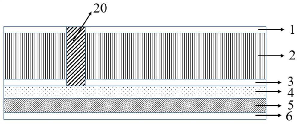
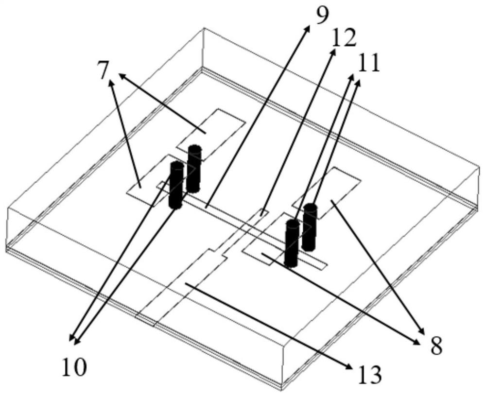
[0025] This specific embodiment discloses a substrate-integrated magnetoelectric dipole antenna based on a low-profile microstrip feed structure, such as Figure 1-Figure 2 As shown, it includes the top metal layer 1, the first dielectric layer 2, the middle metal layer 3, the second dielectric layer 4, the third dielectric layer 5 and the bottom metal layer 6 arranged in sequence from top to bottom, wherein the top metal layer 1 There is a pair of printed electric dipoles on it, including the first group of electric dipoles 7 and the second group of electric dipoles 8, the middle metal layer 3 is the ground layer, and the excitation printed electric dipoles are etched on it. The rectangular slots 9 of the printed circuit ...


PUM

PropertyMeasurementUnit
thicknessaaaaaaaaaa
thicknessaaaaaaaaaa
thicknessaaaaaaaaaa

Abstract

The invention discloses a substrate integrated electric dipole antenna based on low-profile microstrip feed structure and an array. The antenna comprises a top metal layer, a first dielectric layer, amiddle metal layer, a second dielectric layer, a third dielectric layer and a bottom metal layer; a pair of printed electric dipoles is arranged at the top metal layer, the middle metal layer is a grounding layer on which a rectangular groove for exciting the printed electric dipoles is etched; the printed electric dipoles are connected with the middle metal layer through a pair of metallized half-blind holes penetrating through the first dielectric layer; the rectangular groove etched on the middle metal layer is located in the middle of the metallized half-blind holes for connecting the printed electric dipoles and the middle metal layer; the middle metal layer, the second dielectric layer, the third dielectric layer and the bottom metal layer form a low-profile microstrip feed structure. More than 40% impedance bandwidth can be acquired, the in-band gain fluctuation is lower than 3dB, and furthermore, the direct integration with a radio frequency front-end circuit is realized through the low-profile microstrip feed structure.

Description

technical field [0001] The invention belongs to microwave and millimeter wave communication, in particular to a substrate-integrated electric dipole antenna and an array based on a low-profile microstrip feeding structure. Background technique [0002] mmWave technology has received tremendous attention in recent years, driven by various practical and potential applications, such as 5G mmWave communications, automotive radar, high-resolution imaging and detection, and some other applications. To achieve high-speed transmission in communication systems and high resolution in automotive radar and imaging applications, wideband electronics are required. In particular, broadband millimeter-wave device antennas, which are key devices in millimeter-wave wireless systems, need to be developed and designed urgently. Among various millimeter-wave antennas, the planar millimeter-wave array antenna is very promising because of its high gain and the advantages of being directly integra...

Claims


Application Information

Patent Timeline
Patent Type & Authority Patents(China)
IPC IPC(8): H01Q1/38H01Q1/48H01Q1/50H01Q9/06H01Q9/16H01Q21/00
Inventor 洪伟徐俊蒋之浩张慧
Owner SOUTHEAST UNIV
Why Eureka
Try Eureka