Base station MIMO antenna unit

A technology of antenna unit and base station, which is applied in the direction of antenna, antenna coupling, antenna array, etc., can solve the problems of unsatisfactory, low profile, high profile, etc., achieve high-efficiency dual-polarized radiation, broaden impedance bandwidth, and meet technical requirements.

Pending Publication Date: 2020-10-30
NO 54 INST OF CHINA ELECTRONICS SCI & TECH GRP
View PDF0 Cites 0 Cited by
  • Summary
  • Abstract
  • Description
  • Claims
  • Application Information

AI Technical Summary

Problems solved by technology

[0004] 1. Dual-polarized half-wave dipole antenna: This type of antenna has a simple structure, a standing wave bandwidth greater than 60%, and high port isolation, but its profile is relatively high, usually around 0.25 wavelengths, and its electrical size is 0.8 wavelengths, which cannot meet 5G requirements. Base station antenna beamforming requirements for electrically small size (0.5 wavelength) of the antenna unit;
[0005] 2. In the form of dual-polarized microstrip antennas, in order to broaden the standing wave bandwidth of the antenna unit, the form based on the microstrip antenna often uses a slot-coupled electromagnetic structure to broaden the bandwidth of the antenna. The standing wave bandwidth is about 20%, and the port isolation Satisfy greater than 25%, because it is an air sandwich structure, the profile is high, and it is not easy to achieve active integration design;
[0006] 3. Magnetically coupled dual-polarized dipole antenna. This form of antenna uses two orthogonally placed L probes to excite two pairs of dipoles with pillars. This shape has a simple structure, wide bandwidth, high port isolation, and low profile, but its The active circuit integrated design cannot be realized, and the electrical size is large, which cannot meet the requirements of 5G base station antenna beamforming on the electrical small size (0.5 wavelength) of the antenna unit
[0007] The above several dual-polarized antenna units have their own advantages and disadvantages. Although individual indicators have better characteristics, their common defect is that they cannot meet the technical requirements of miniaturized wide-band work, especially as broadband, ultra-low profile, and active integration. None of the base station MIMO system antenna units can meet all technical index requirements

Method used


Image

  • Base station MIMO antenna unit
  • Base station MIMO antenna unit
  • Base station MIMO antenna unit

Examples


Embodiment Construction

[0024] Below, the present invention will be further described in conjunction with the accompanying drawings and specific embodiments.

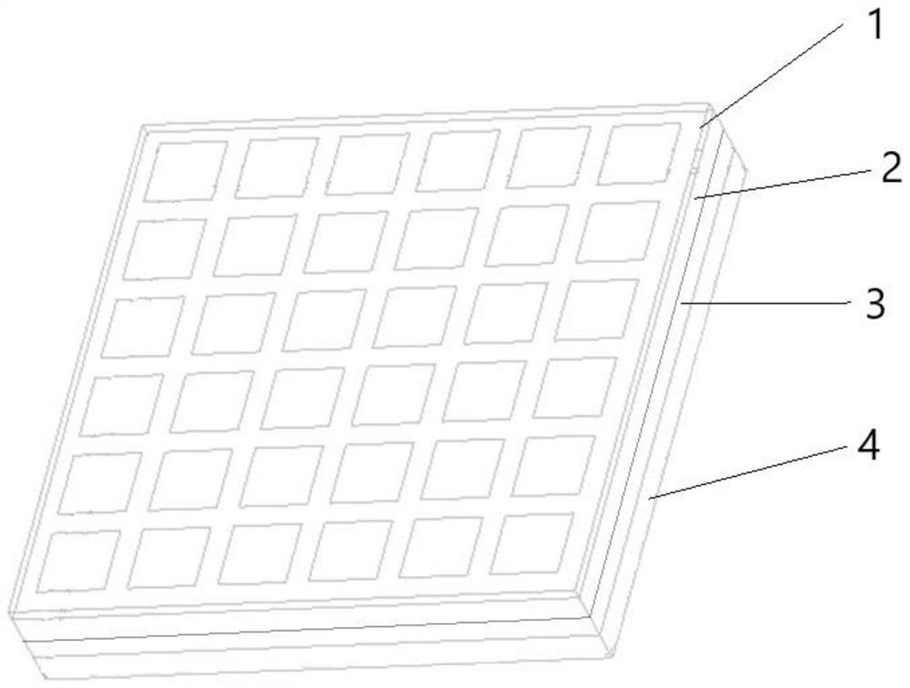
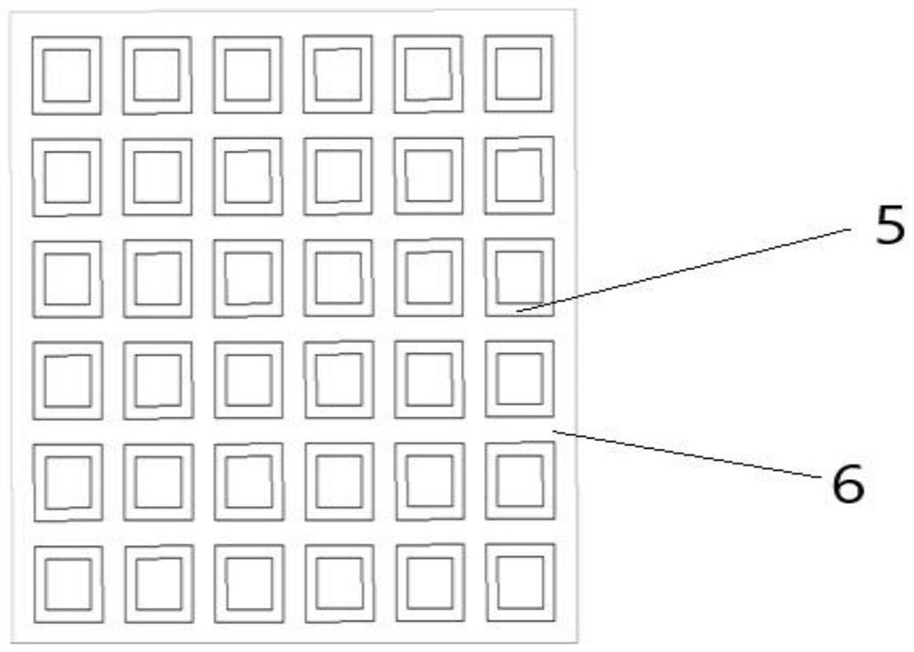
[0025] A base station MIMO antenna unit, comprising a loading layer 1, a radiation layer 2, a feeding network layer 3 and a metal formation 4 arranged in sequence from top to bottom; the main body of the loading layer is a microwave dielectric board 6, and the microwave dielectric board The upper surface is provided with metal loading units 5 arranged in a rectangular array, and the metal loading units are square ring structures;

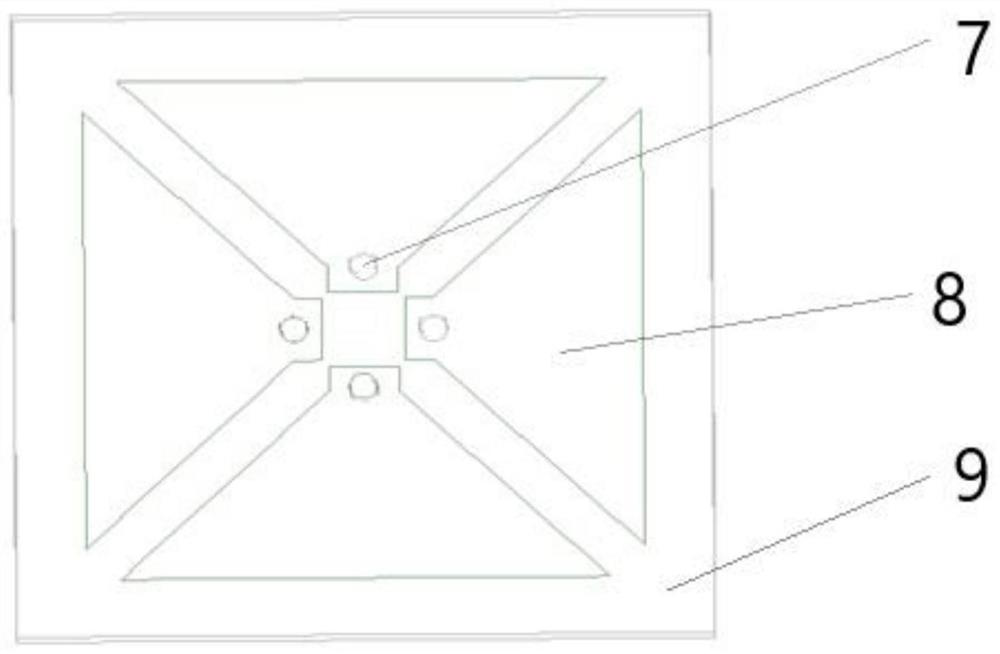
[0026] The main body of the radiation layer is a second dielectric plate, and four vibrator structures arranged in a circular array are arranged on the upper surface of the second dielectric plate 9; each vibrator 8 structure includes a rectangular feeding end and an isosceles The radiating end of the trapezoidal structure, the feeding end is located at the center of the upper surface of the second dielectric plate,...


PUM


Abstract

The invention discloses a base station MIMO antenna unit, and belongs to the technical field of antennas. The antenna unit comprises a radio frequency connector, and a loading layer, a radiation layer, a feed network layer and a metal ground layer which are sequentially arranged from top to bottom. The base station MIMO antenna unit has the characteristics of the compact and simple structure and the small electrical size, has a dual-polarized radiation function, and can meet the strict technical requirements of the digital multi-beam antenna on the radiation unit.

Description

technical field [0001] The invention relates to the technical field of antennas, in particular to a MIMO antenna unit for an office base station. Background technique [0002] Since the commercial use of the communication system is imminent, the design of the antenna has attracted the attention of many scholars. Most of them are four-port and eight-port antennas. The MIMO antenna terminal antenna with large electrical size cannot be used in the beamforming base station antenna system. The scene is a handheld terminal, an IoT terminal, and the technical characteristics of four-port and eight-port are high antenna port isolation and symmetrical pattern. Due to the complexity of the feeding network and the large space occupied, the antenna cannot achieve an electrically small size design. . [0003] At this stage, base station MIMO antennas mainly have the following forms: [0004] 1. Dual-polarized half-wave dipole antenna: This type of antenna has a simple structure, a stan...

Claims


Application Information

Patent Timeline
Patent Type & Authority Applications(China)
IPC IPC(8): H01Q1/24H01Q1/36H01Q1/38H01Q1/48H01Q1/50H01Q1/52H01Q21/00H01Q21/06
CPCH01Q1/246H01Q1/36H01Q1/38H01Q1/48H01Q1/50H01Q1/52H01Q21/0006H01Q21/061
Inventor 宋长宏翟会清习磊张文静
Owner NO 54 INST OF CHINA ELECTRONICS SCI & TECH GRP
Why Eureka
Try Eureka