An ultra-broadband circularly polarized cavity-backed crossed-dipole antenna

A cross-dipole and circular polarization technology, which is applied to antennas, leaky waveguide antennas, electrical components, etc., can solve the problems of insufficient antenna bandwidth and large antenna size, and achieve the effects of miniaturization design, easy integration, and compact structure

Active Publication Date: 2022-05-10
INST OF APPLIED ELECTRONICS CHINA ACAD OF ENG PHYSICS
View PDF11 Cites 0 Cited by
  • Summary
  • Abstract
  • Description
  • Claims
  • Application Information

AI Technical Summary

Problems solved by technology

[0005] Aiming at the problem that the existing crossed dipole antenna has insufficient bandwidth and large antenna size, the present invention proposes an ultra-wideband circularly polarized cavity-backed crossed dipole antenna, which has ultra-wideband impedance bandwidth and axial ratio bandwidth. Not only can the relative bandwidth be as high as 125.2% impedance bandwidth and 120.1% axial ratio bandwidth, but also has a compact structure with a relative size of 0.54λ 0 ×0.54λ 0 ×0.23λ 0 , easy to promote the development of high-confidence testing technology for complex electromagnetic environments

Method used


Image

  • An ultra-broadband circularly polarized cavity-backed crossed-dipole antenna
  • An ultra-broadband circularly polarized cavity-backed crossed-dipole antenna
  • An ultra-broadband circularly polarized cavity-backed crossed-dipole antenna

Examples


Embodiment Construction

[0031] In order to have a clearer understanding of the technical features, purposes and effects of the present invention, specific implementations of the present invention are now described. It should be understood that the specific embodiments described here are only used to explain the present invention, and are not intended to limit the present invention, that is, the described embodiments are only some of the embodiments of the present invention, but not all of the embodiments. Based on the embodiments of the present invention, all other embodiments obtained by those skilled in the art without making creative efforts belong to the protection scope of the present invention.

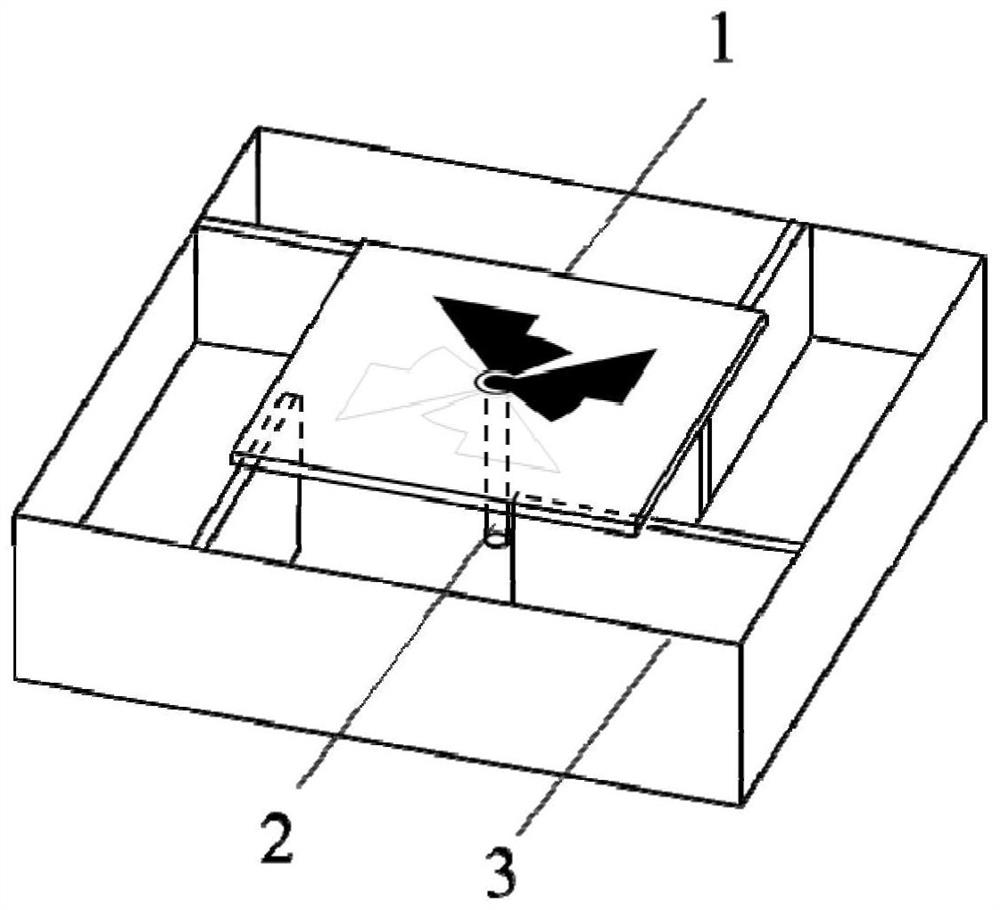
[0032] This embodiment provides an ultra-wideband circularly polarized cavity-backed crossed dipole antenna, such as figure 1 As shown, it includes crossed dipole 1, coaxial transmission line 2 and composite back cavity 3, crossed dipole 1 is placed above the composite back cavity 3, and coaxial trans...


PUM


Abstract

The invention discloses a novel ultra-broadband circularly polarized cavity-backed crossed dipole antenna, which includes a crossed dipole, a coaxial transmission line, and a composite back cavity. The crossed dipole is placed above the composite back cavity. The coaxial transmission line is connected to the crossed dipole after passing through the composite back cavity; the crossed dipole includes a dielectric plate, a phase delay line and a plurality of metal radiation arms, and the plurality of metal radiation arms are evenly located On the upper and lower sides of the dielectric plate, the metal radiation arms located on the same side are connected by the phase delay line, so that orthogonal phases are generated between the metal radiation arms to excite circularly polarized electromagnetic waves. The cross dipole antenna of the present invention can realize ultra-wideband impedance bandwidth and axial ratio bandwidth, which is of great significance for further broadening the application field of the cross dipole antenna. The cross dipole antenna of the present invention has a very compact structure, is easy to integrate with the system, and is beneficial to the miniaturization design of the system.

Description

technical field [0001] The invention relates to the technical field of electromagnetic environment perception and testing, in particular to an ultra-wideband circularly polarized cavity-backed crossed dipole antenna. Background technique [0002] Compared with linearly polarized antennas, circularly polarized antennas have the advantages of anti-multipath interference and eliminating polarization mismatch. At the same time, in the transceiver system, when using circularly polarized antennas, there are no strict requirements on the alignment of the transceiver antennas. Based on the above excellent characteristics, circularly polarized antennas have been widely used in electromagnetic environment perception and testing, and wireless communication systems. However, due to the extensive use of electronic systems, they will radiate electromagnetic signals with wide frequency bands, different energies, and different polarizations into space when they work, making the space electr...

Claims


Application Information

Patent Timeline
Patent Type & Authority Patents(China)
IPC IPC(8): H01Q1/38H01Q13/20
CPCH01Q1/38H01Q13/203
Inventor 范均秦风林江川蔡金良高原赵刚严志洋吴双
Owner INST OF APPLIED ELECTRONICS CHINA ACAD OF ENG PHYSICS
Why Eureka
Try Eureka