Integrated electric servo brake system for vehicle

A technology that integrates electric and braking systems. It is applied to brakes, vehicle components, and brake transmissions. It can solve problems such as frequent use and poor reliability, and achieve the effects of increasing speed, maintaining foot feel, and good foot feel.

Inactive Publication Date: 2019-06-25
WANXIANGQIANCHAO CO LTD +1
View PDF8 Cites 7 Cited by
  • Summary
  • Abstract
  • Description
  • Claims
  • Application Information

AI Technical Summary

Problems solved by technology

[0007] The purpose of the present invention is to provide a vehicle integrated electric servo braking system, which solves the defect of poor reliability caused by the frequent use of components such as high-voltage accumulators in the existing vehicle integrated electric servo braking system

Method used


Image

  • Integrated electric servo brake system for vehicle
  • Integrated electric servo brake system for vehicle
  • Integrated electric servo brake system for vehicle

Examples


Embodiment 1

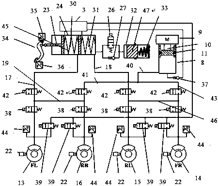
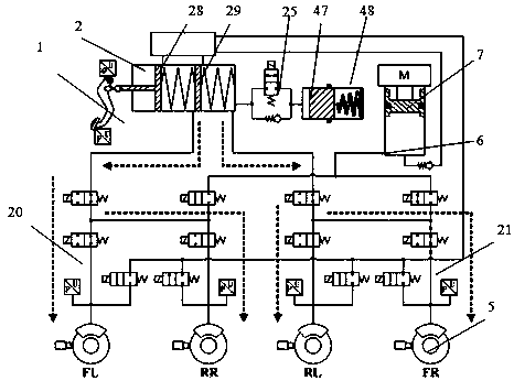
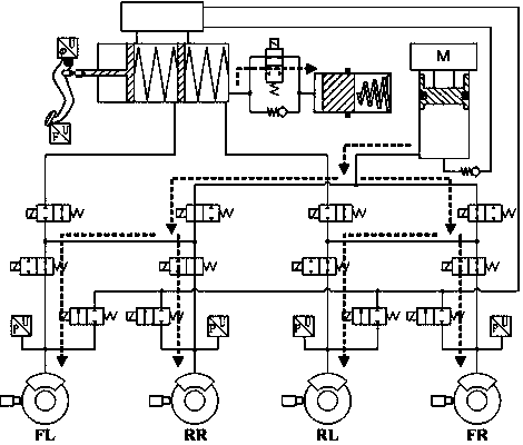
[0052] Embodiment 1: The present invention provides a vehicle integrated electric servo braking system, including: a brake operating mechanism 1; a brake master cylinder assembly 2, including a liquid storage tank 3; Master cylinder assembly; wheel brake assembly 4, including brake wheel cylinder 5; the brake master cylinder assembly communicates with the brake wheel cylinder; hydraulic circuit 6, including a booster module 7; wherein, the booster module includes A booster cylinder 8, a motor 9 and a ball screw 10 rigidly connected to the motor, the booster cylinder is provided with a hydraulic piston 11; the hydraulic piston 11 is installed inside the cylinder of the ball screw; The motor drives the ball screw to move, so that the ball screw drives the hydraulic piston to move; one end of the booster module is connected to the liquid storage tank, and the other end is connected to the brake wheel cylinder.

Embodiment 2

[0053] Embodiment 2: as figure 1 , Figure 5 As shown, the present invention provides a vehicle integrated electric servo braking system. The present invention provides a vehicle integrated electric servo braking system, including: a brake operating mechanism; a brake master cylinder assembly and an electronic control unit 12, including Liquid storage tank; the brake control mechanism transmission connection brake master cylinder assembly; wheel brake assembly, including the brake wheel cylinder; the brake master cylinder assembly is connected to the brake wheel cylinder; hydraulic circuit, including the booster module; wherein, the supercharging module includes a supercharging cylinder, a motor and a ball screw rigidly connected to the motor, and a hydraulic piston is arranged in the supercharging cylinder; the said supercharging module is installed inside the cylinder of the ball screw; the said The ball screw is also connected to the hydraulic piston, and the motor drives ...


PUM


Abstract

The invention provides an integrated electric servo brake system for a vehicle. The system comprises a brake operating mechanism, a brake main cylinder assembly, a wheel brake assembly and a hydraulicloop. The brake main cylinder assembly comprises a liquid storage tank; the brake operating mechanism is in transmission connection with the brake main cylinder assembly; the wheel brake assembly includes a brake wheel cylinder; the brake main cylinder assembly is communicated with the brake wheel cylinder; the hydraulic loop includes a supercharging module; the supercharging module comprises a supercharging cylinder body, a motor and a ball screw which is in rigid connection with the motor, wherein a hydraulic piston is arranged in the supercharging cylinder body and installed on the inner side of a ball screw cylinder body; the ball screw is also connected with the hydraulic piston, the motor drives the ball screw to move, and correspondingly the ball screw drives the hydraulic piston to move; one end of the supercharging module is communicated with the liquid storage tank, and the other end of the supercharging module is communicated with the brake wheel cylinder. The whole reliability of the system is improved, and working noise, installation volume and weight are reduced.

Description

technical field [0001] The invention relates to the field of new energy vehicle braking systems, in particular to a vehicle integrated electric servo braking system. Background technique [0002] In the current car market, the braking system of most cars has been powered by the engine-driven vacuum booster pump for 40 years. The potential for reducing costs and improving functions under this principle is already very small. The market potential of pure electric / hybrid vehicles in the future is huge. While continuing to use the existing vacuum booster / electronic vacuum booster structure, OEMs urgently need a new type of brake-by-wire system that can not only reduce cost, size, and energy consumption, but also seamlessly cooperate to achieve braking energy recovery, auxiliary Braking, active braking and other advanced functions. [0003] The brake-by-wire system was first proposed in the late 1980s, and has been recognized as the development trend of the future brake system....

Claims


Application Information

Patent Timeline
Patent Type & Authority Applications(China)
IPC IPC(8): B60T13/12B60T13/138B60T13/68
Inventor 张杰刘伟刘宏伟张成才陈斌孙道远刘兵
Owner WANXIANGQIANCHAO CO LTD
Why Eureka
Try Eureka