Turning conveyor and conveyor belt

A conveyor belt and conveyor technology, applied in the field of logistics conveyors, can solve the problems of excessive tension and easy wear, conveyor belt deviation, easy deviation, etc., to eliminate slippage, prolong service life, and reduce energy consumption. Effect

Pending Publication Date: 2019-06-25
AA IND BELTING (SHANGHAI) CO LTD
View PDF3 Cites 4 Cited by
  • Summary
  • Abstract
  • Description
  • Claims
  • Application Information

AI Technical Summary

Problems solved by technology

However, it still cannot solve the problem of conveyor belt deviation. Moreover, since the conveyor belt is flat, its movement still depends on the friction with the guide shaft, so the problem of easy wear caused by excessive tension cannot be alleviated.
[0006] Patent No. CN 201820109606.2, named as a utility model patent for a new type of curve conveyor, discloses a curve conveyor, including a reinforced conveyor belt and a turning roller. One side of the reinforced conveyor belt is fixed with a No. 1 peripheral guardrail. And the other side of the enhanced conveyor belt is fixedly installed with No. 2 peripheral guardrail, trying to solve the problem of conveyor belt deviation. The outer surface of the No. 1 peripheral guardrail is provided with a variable speed runner and a power box. One of the No. 2 peripheral guardrails There is a motor near the end of the side outer surface, and a steel wire rope is installed inside the conveyor belt to form a reinforcement layer, which makes the conveyor belt tough and not easy to break. It is suitable for the use of curves and other measures to solve the problems of conveyor belt power and reduce wear, but it cannot effectively solve the problem of excessive tension in the curve conveyor, the conveyor belt is easy to slip, easy to wear, and the conveyor belt is prone to lateral displacement and deviation. ills

Method used


Image

  • Turning conveyor and conveyor belt
  • Turning conveyor and conveyor belt
  • Turning conveyor and conveyor belt

Examples


Embodiment approach 1

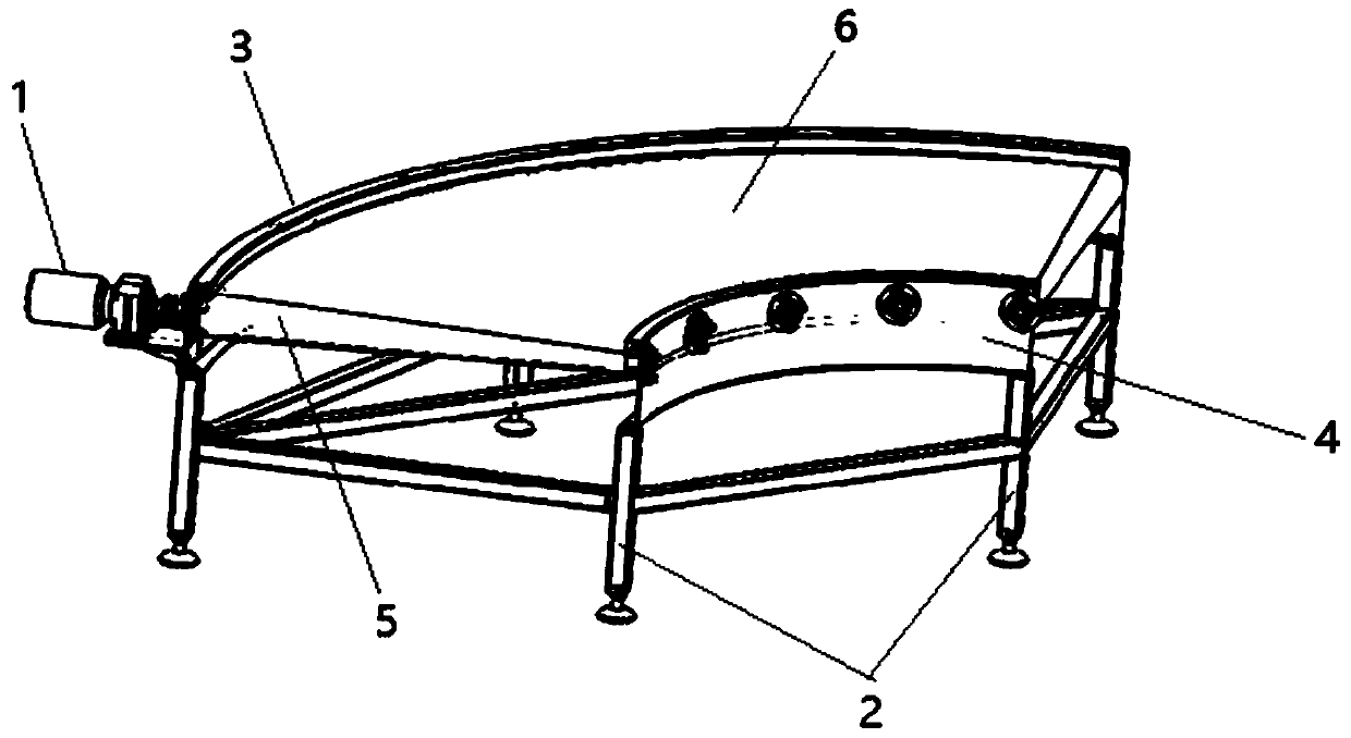
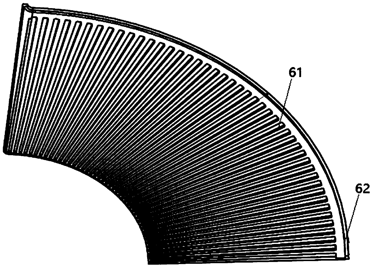
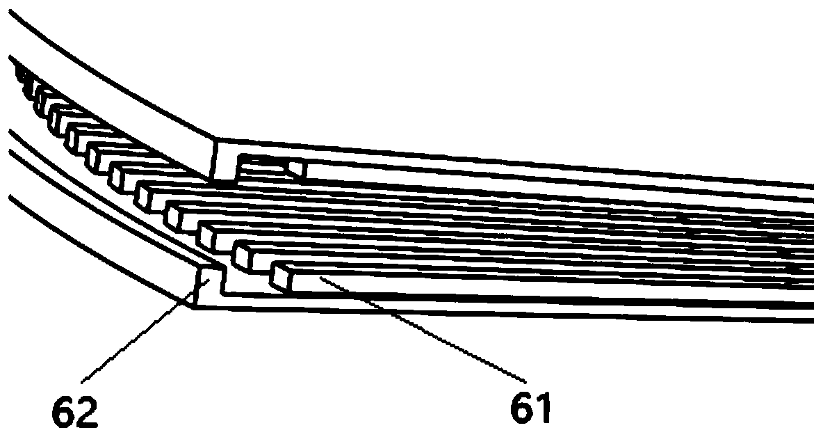
[0060] Embodiment 1, such as Figure 4 As shown, the belt pressing mechanism is arranged on the outer ring support 3 and the bead 7 opposite to the outer surface of the fan-shaped conveyor belt 6, and the bead 7 is arranged above the outer edge of the fan-shaped conveyor belt 6 to prevent the conveyor belt from upturning. The guide strip limit mechanism is a limit guide plate 8 arranged on the outer ring support 4 against the inner surface of the longitudinal guide bar 62, and the limit guide plate 8 is against the inner surface of the longitudinal guide bar 62, so that the conveying There is no lateral displacement of the belt, and it will not deviate inward.

Embodiment approach 2

[0061] Embodiment 2, such as Figure 5 As shown, the belt pressing mechanism is a pressure roller 9 arranged on the outer ring support 3 opposite to the outer surface of the fan-shaped conveyor belt 6, and the guide strip limit mechanism is arranged on the outer ring support 3 The position-limiting guide wheels 10 mortgaged on the inner side of the longitudinal guide bar 62 , the pressure wheels 9 and the position-limiting guide wheels 10 should be provided in multiple sets on the outer ring support 3 .

Embodiment approach 3

[0062] Embodiment 3, such as Image 6 As shown, the belt pressing mechanism is arranged on the outer ring support 3 and opposite to the outer surface of the fan-shaped conveyor belt 6. The bar limit mechanism is arranged on the outer ring support and mortgaged The limit guide wheels 10 on the inner side of the longitudinal guide bar 62, the limit guide wheels 10 should be provided with multiple groups on the outer ring support 3.


PUM


Abstract

The invention relates to a turning conveyor. The turning conveyor comprises a conveyor machine frame, a drive system, a fan-shaped conveyor belt and transmission guide shafts. The machine frame comprises a fan-shaped frame. The transmission guide shafts are arranged in the fan-shaped frame. Tooth grooves are formed in the axial surface of each transmission guide shaft. The invention further relates to a conveyor belt suitable for the turning conveyor mentioned above. Transverse racks are arranged on the inner surface of the conveyor belt and are meshed with the axial tooth grooves of the transmission guide shafts. The corresponding transmission guide shaft is connected with the drive system, and the fan-shaped conveyor belt is driven to cyclically rotate around the transmission guide shafts in the fan-shaped frame to be used for conveying goods; by means of gear transmission achieved through meshing of the tooth grooves of the transmission guide shafts and the racks of the fan-shaped conveyor belt, rotation of the conveyor belt can be easy, and the friction loss between the conveyor belt and the transmission shafts is greatly reduced; and meanwhile the conveyor belt is provided with longitudinal guide strips, a conveyor belt limiting mechanism is arranged on the machine frame, and the problem that transverse displacement and deviation are caused to the conveyor belt during curve operation is thoroughly solved through combination of the longitudinal guide strips and the conveyor belt limiting mechanism.

Description

technical field [0001] The invention provides a curved conveyor and a conveyor belt, which relate to the field of logistics conveyors. Background technique [0002] Belt conveyors are widely used. They can transport bulk materials as well as finished items. They can run continuously or cooperate with the process in the production process to form a rhythmic assembly line. Its structure It roughly includes conveyor belts, head rollers, tail rollers, driving rollers, driving devices, trough roller sets, lower rollers, and frame structures. Connected as the driving roller, the driving roller is generally arranged at the discharge end, so that the working side is the tight side, the conveyor belt is wound between each roller, the grooved roller group and the lower idler roller are arranged between each roller, and the conveyor belt is straight It is used to support the self-weight of the conveyor belt and the weight of the material. The working side and the non-working side of t...

Claims


Application Information

Patent Timeline
Patent Type & Authority Applications(China)
IPC IPC(8): B65G39/16B65G15/64B65G15/30
Inventor 涂国圣陈新新吴惠平
Owner AA IND BELTING (SHANGHAI) CO LTD
Why Eureka
Try Eureka