Anti-blocking sewer

A sewer and anti-blocking technology, applied in the municipal field, can solve the problems of sediment accumulation and easy blockage, and achieve the effects of improving convenience, improving installation efficiency, good mechanical properties and economical efficiency

Inactive Publication Date: 2019-06-25
张婷
View PDF8 Cites 2 Cited by
  • Summary
  • Abstract
  • Description
  • Claims
  • Application Information

AI Technical Summary

Problems solved by technology

However, due to the large amount of debris in the sewer, it is easy to block and has always been a world problem that has plagued all countries.
[0003] Chinese patent (notification number: CN 206916784 U, announcement date: 2018.01.23) discloses an anti-clogging sewer manhole cover. The body, the cover body and the anti-blocking layer are hollow inside. The cover body is provided with drain grids, anti-skid strips and

Method used


Image

  • Anti-blocking sewer
  • Anti-blocking sewer
  • Anti-blocking sewer

Examples


Embodiment 1

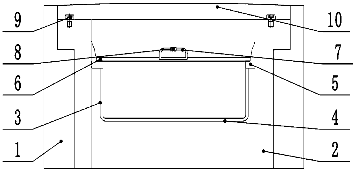
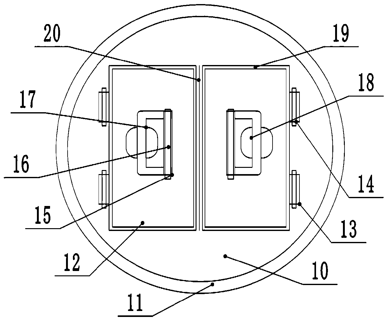
[0020] see figure 1 , an anti-clogging sewer, comprising: a concrete layer 1, a sewer inner wall 2, a well cover 10 and a well cover flange 11, the concrete layer 1 is the basic structure of a sewer engineering, and the inner circle of the concrete layer 1 is provided with a sewer inner wall 2, the said The inner wall 2 of the sewer is made of polyester fiber pipe, which has a smooth surface, is not easy to accumulate impurities, and has good corrosion resistance. In addition, there are installation steps between the top of the concrete layer 1 and the inner wall 2 of the sewer to improve the installation efficiency. The well cover 10 is fixedly installed by the fixing bolt 9, and the well cover 10 is made of cast iron, which has good mechanical properties and economy, such as figure 2 As shown, the outside of the well cover 10 is provided with a well cover flange 11, and the edge of the well cover flange 11 has a raised structure, which effectively protects the force of the ...

Embodiment 2

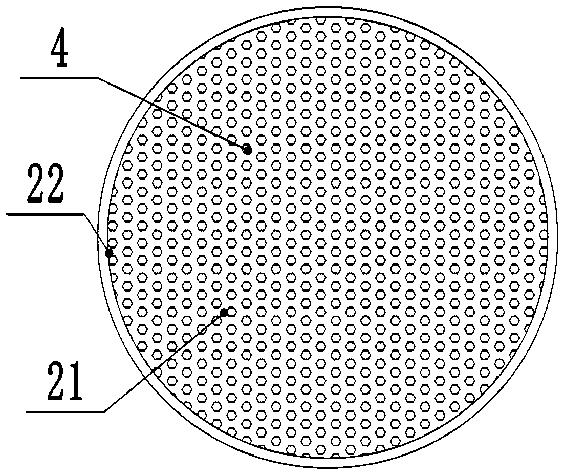
[0023] Compared with Embodiment 1, the embodiment 2 differs only in that the collecting tank 3 is of an aluminum alloy structure, and water outlet holes are evenly distributed on the edge, which is convenient for draining when the bottom of the collecting tank bottom plate 4 is blocked, and improves anti-clogging Ability.

[0024] Technical principle: Turn and pull up the cover plate handle 17 along the rotation groove 16 by hollowing out the groove 18, rotate the cover plate 12 along the hinge rotation axis 14 through the cover plate handle 17, open the middle of the well cover 10, and pass through the positioning groove 8 After positioning, use the hook to lift the handle 7 and take out the collection tank 3 as a whole, clean up the impurities filtered inside, effectively avoid the blockage of the pipeline, the structure is stable and reliable, the operation is simple and efficient, and it has good practical value.


PUM


Abstract

The invention relates to the field of municipal administration, and specifically relates to an anti-blocking sewer. The anti-blocking sewer comprises a concrete layer, a sewer inner wall, a manhole cover and a manhole cover flange, wherein hinges are symmetrically arranged inside the manhole cover, hinge rotation shafts are rotatably mounted in the hinges, cover plates are rotatably mounted on theouter rings of the hinge rotation shafts, cover plate side edges are fixedly mounted on the outer rings of the cover plates, handle rotation shafts are arranged on the middle part of the cover plates, handles are rotatably mounted on the two ends of rotation grooves, installation clamping blocks are arranged on the inner ring of the sewer inner wall, the installation clamping blocks are of a convex structure, a flange is arranged on the outer ring of the upper end of a material collection tank, and a material collection tank bottom plate is arranged at the bottom of the material collection tank. The entire material collection tank is taken out by using a hook to lift the handles after locating through a locating slot, internally-filtered impurities are cleared, a pipeline is effectively prevented from being blocked, the structure is stable and reliable, the operation is simple and efficient, and good practical value is realized.

Description

technical field [0001] The invention relates to the field of municipal administration, in particular to an anti-clogging sewer. Background technique [0002] The sewer is a kind of urban public facility, which refers to the pipes used by buildings to discharge sewage and rainwater; it also refers to the underground passages used by cities, factories or villages to discharge sewage and rainwater. The sewer is a kind of urban public facility, which existed as early as in ancient Rome Appear. The embryonic form of modern sewers originated in Paris, France, and Paris still has the world's largest urban sewer system. However, due to the large amount of debris in the sewer, it is easy to block and has always been a world problem that has plagued various countries. [0003] Chinese patent (notification number: CN 206916784 U, announcement date: 2018.01.23) discloses an anti-clogging sewer manhole cover. The body, the cover body and the anti-blocking layer are hollow inside. The ...

Claims


Application Information

Patent Timeline
IPC IPC(8): E03F5/04E03F5/06E03F5/14E03F1/00
Inventor 张婷冉海南
Owner 张婷
Why Eureka
Try Eureka