
LED lens and lighting device

A technology of LED lens and lighting device, which is applied to lighting device, lighting device parts, lighting and heating equipment, etc., can solve the problem of large lighting angle of lighting device, and achieve the effect of small lighting angle and good lighting effect.

Pending Publication Date: 2019-06-25
GUANGDONG INST OF SEMICON IND TECH
View PDF8 Cites 4 Cited by
  • Summary
  • Abstract
  • Description
  • Claims
  • Application Information

AI Technical Summary

Problems solved by technology

[0005] The purpose of the present invention is to provide an LED lens to solve the problem of large light emitting angle of the lighting device in the prior art
[0006] Another object of the present invention is to provide an illuminating device to solve the problem that the illuminating device in the prior art has a relatively large luminous angle

Method used


Image

  • LED lens and lighting device
  • LED lens and lighting device
  • LED lens and lighting device

Examples


no. 1 example

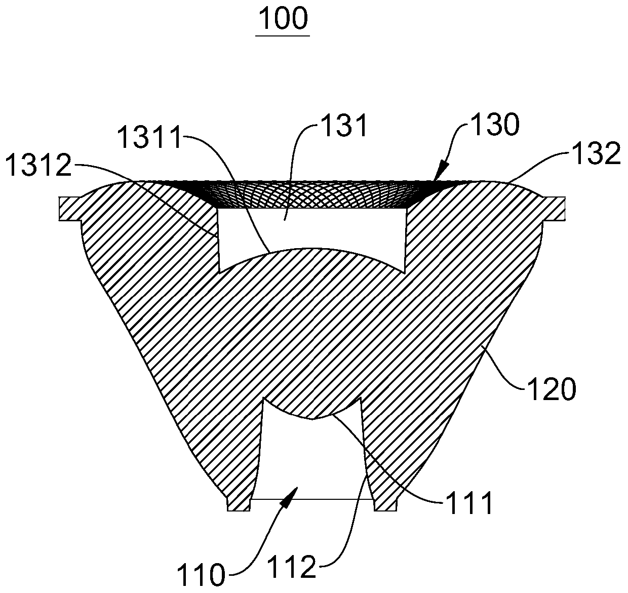
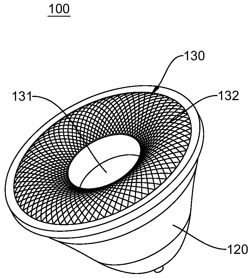
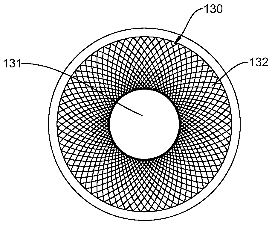
[0032] see figure 1 , the embodiment of the present invention provides an LED lens 100, the LED lens 100 includes an accommodating cavity 110, a total reflection surface 120, and a second refraction portion of the light exit surface 130, wherein the accommodating cavity 110 is arranged at one end of the total reflection surface 120 The light emitting surface 130 is disposed on the other end of the total reflection surface 120 , and the accommodating cavity 110 , the total reflection surface 120 and the light exit surface 130 are sequentially connected to the total reflection surface 120 of the second refraction portion.

[0033]Specifically, in this embodiment, the accommodating cavity 110 is used to install an LED light source 210, and at the same time, one end of the accommodating cavity 110 close to the total reflection surface 120 is provided with a first refracting portion 111 protruding in a direction away from the light-emitting surface 130 , the first refraction portio...

no. 2 example

[0048] see Figure 4 , the embodiment of the present invention also provides an illuminating device 200 , the illuminating device 200 includes an LED light source 210 and the LED lens 100 described in the first embodiment, and the LED light source 210 is installed in the accommodating cavity 110 . After the light emitted by the LED light source 210 passes through the LED lens 100, it can be reflected by the total reflection surface 120 on the side of the lens body and spread to the light-emitting surface. The narrow beam is projected out, and the ultra-small angle beam projection of less than 3° can be realized under the conventional lens size. It has a good uniform light and color mixing effect, and can be widely used in LED outdoor floodlights, entertainment par lights, wall washers, Matrix lights etc.

[0049] In summary, the present invention provides an LED lens and lighting device. The LED lens includes an accommodating cavity, a total reflection surface, and a light ou...


PUM


Abstract

The invention provides an LED lens and a lighting device, and relates to the technical field of LEDs. The LED lens comprises a containing cavity, a fully reflecting surface and a light emitting surface, the containing cavity is arranged at one end of the fully reflecting surface, the light emitting surface is arranged at the other end of the fully reflecting surface, the light emitting surface isarranged to be an arc convex surface sunk along the fully reflecting surface, the containing cavity is used for mounting of an LED light source, the end, close to the fully reflecting surface, of thecontaining cavity is provided with a first refracting portion protruding in the direction far away from the light emitting surface, a part of light emitted by the LED light source is refracted by thefirst refracting portion to be diffused to the light emitting surface, the other part of the light emitted by the LED light source is reflected by the fully reflecting surface to be diffused to the light emitting surface, and the light is refracted by the light emitting surface to be diffused out. The LED lens and the lighting device have the advantages that the light emitting angle of the entirelighting device is small, and the light emitting effect is better.

Description

technical field [0001] The invention relates to the technical field of LEDs, in particular to an LED lens and an illuminating device. Background technique [0002] In modern lighting applications, with the implementation of the incandescent lamp phase-out plan, LED lighting has gradually become popular. Compared with traditional lighting, LED lighting has significant advantages in energy saving, environmental protection and long life. Energy saving, so LED lighting has been widely used in shopping malls, hotels, hospitals, roads, architectural landscapes, stage lighting and other lighting fields. [0003] Due to the large power required for stage entertainment lighting and outdoor landscape lighting, in order to realize this kind of high-power LED lighting, there are currently two technologies: packaging a single high-power LED chip or adopting multi-chip integrated packaging. For the former, The realization of high power is often limited by the size of the chip, while inte...

Claims


Application Information

Patent Timeline
Patent Type & Authority Applications(China)
IPC IPC(8): F21V5/04F21Y115/10
Inventor 夏智锋张志清许毅钦陈志涛张强古志良洪宇许平
Owner GUANGDONG INST OF SEMICON IND TECH
Learn More