Power generation fabric structure and preparation method thereof

A technology of fabric structure and conductive fabric, applied in the directions of generators/motors, knitting, electrical components, etc., can solve the problems of mutual contact of multiple piezoelectric yarns, short circuit of smart fabrics, affecting the user experience of smart fabrics, etc. The effect of avoiding short circuit phenomenon and improving collection efficiency

Active Publication Date: 2019-06-25
JIAXING UNIV
View PDF6 Cites 2 Cited by
  • Summary
  • Abstract
  • Description
  • Claims
  • Application Information

AI Technical Summary

Problems solved by technology

[0005] In the power-generating fabric structure provided by related technologies, the piezoelectric potential difference is generated from both ends of the piezoelectric yarn. When the power-generating fabric structure is applied to smart fabrics, it is easy for multiple piezoelectric yarns to contact each other due to improper operation by the user. Short circuit occurs in smart fabrics, which seriously affects the user experience of smart fabrics

Method used


Image

  • Power generation fabric structure and preparation method thereof
  • Power generation fabric structure and preparation method thereof
  • Power generation fabric structure and preparation method thereof

Examples


preparation example Construction

[0034] Figure 4 It is a method flow chart of a method for preparing a power generating fabric structure shown according to an exemplary embodiment, as shown in Figure 4 As shown, the preparation method of the power generating fabric structure comprises:

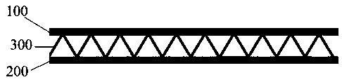
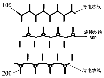
[0035] Step 401: Weaving a first conductive fabric and a second conductive fabric with conductive yarns.

[0036] The conductive yarn is one of silver-plated conductive yarn and polyamide / stainless steel staple fiber blended yarn.

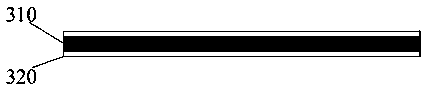
[0037] Step 402: using the core electrode as the core layer and the PVDF fiber as the shell layer to prepare a connecting yarn with a shell-core structure.

[0038] Step 403: Ground the core electrode of the connected yarn, and polarize it with a voltage of 6kV for 4 minutes. The direction of the polarized electric field is from the shell layer of the connected yarn to the core layer. After polarization, the connected yarn is clamped between two pieces of grounded metal The surface decharge t...

Embodiment 1

[0044] (1) The first conductive fabric and the second conductive fabric are respectively woven with silver-plated conductive yarns.

[0045] (2) Using carbon black / polyethylene as the core layer and PVDF fiber as the shell layer, a connecting yarn with a shell-core structure was prepared.

[0046] (3) The core electrode of the connecting yarn is grounded, and a voltage of 6kV is used to polarize for 4 minutes. The direction of the polarized electric field is from the shell layer of the connecting yarn to the core layer. The surface decharge treatment was carried out between two grounded metal plates for 5 minutes, and the direction of the dipoles in the connecting yarn after the surface decharge treatment was directed from the shell layer to the core layer.

[0047] (4) Using the connecting yarn to connect the first conductive fabric and the second conductive fabric, and connecting the conductive yarns in the first conductive fabric and the second conductive fabric through wir...

Embodiment 2

[0050] (1) Using polyamide / stainless steel staple fiber blended yarn to weave the first conductive fabric and the second conductive fabric respectively.

[0051] (2) Using graphene / polyethylene as the core layer and PVDF fiber as the shell layer, a connecting yarn with a shell-core structure was prepared.

[0052] (3) The core electrode of the connecting yarn is grounded, and a voltage of 6kV is used to polarize for 4 minutes. The direction of the polarized electric field is from the shell layer of the connecting yarn to the core layer. The surface decharge treatment was carried out between two grounded metal plates for 5 minutes, and the direction of the dipoles in the connecting yarn after the surface decharge treatment was directed from the shell layer to the core layer.

[0053] (4) Using the connecting yarn to connect the first conductive fabric and the second conductive fabric, and connecting the conductive yarns in the first conductive fabric and the second conductive f...


PUM


Abstract

The invention discloses a power generation fabric structure and a preparation method thereof, and relates to the technical field of piezoelectric intelligent fabrics. According to the power generationfabric structure and the preparation method thereof, a core electrode is used as a core layer; a first conductive fabric and a second conductive fabric are woven by the PVDF fibers which are used asconnecting yarns and conductive yarns of a shell layer, so as to jointly prepare a power generation fabric structure; a core electrode in the polarized connecting yarns is used as an output electrode;the conductive yarns in the first conductive fabric and the second conductive fabric are used as another electrode so that charges with opposite polarities are generated between the inner surface andthe outer surface of the PVDF fiber shell layer of the connecting yarn due to a piezoelectric effect when the first conductive fabric and the second conductive fabric are deformed under the action ofexternal force, and a potential difference is formed, thereby generating a current. After the power generation fabric structure is used for an intelligent fabric, due to the fact that the piezoelectric potential difference comes from the inner surface and the outer surface of the PVDF fiber shell layer, the unique power generation structure can avoid the short circuit phenomenon, and the charge collection efficiency is high.

Description

technical field [0001] The invention relates to the technical field of piezoelectric smart fabrics, in particular to a power generating fabric structure and a preparation method thereof. Background technique [0002] Smart fabrics are textiles and garments developed through interdisciplinary and interactive fields. It is necessary to innovate the textile structure by integrating sensing, driving, electronics, energy and other factors. Because of its multi-functional, light and comfortable wearing characteristics, smart fabrics are regarded as the promoters of high quality of life and the development of biomedicine. [0003] The power generating fabric structure can generate electric field due to mechanical deformation, and can also generate mechanical deformation due to the action of electric field. This inherent electromechanical coupling effect makes piezoelectric materials have been used to make smart structures. In addition to self-supporting capacity, such structures ha...

Claims


Application Information

Patent Timeline
Patent Type & Authority Applications(China)
IPC IPC(8): H02N2/18H02N2/00D04B1/14
Inventor 史晶晶杨恩龙易洪雷
Owner JIAXING UNIV
Why Eureka
Try Eureka