
A 10G EPON asymmetric ONU emission optical eye diagram quality verification method

A technology of eye diagram quality and verification method, applied in electromagnetic wave transmission systems, electromagnetic receivers, electrical components, etc., can solve the problems of frequency points where noise cannot be seen, noise frequency points are not displayed, etc.

Inactive Publication Date: 2019-06-25
SICHUAN TIANYI COMHEART TELECOM
View PDF0 Cites 2 Cited by
  • Summary
  • Abstract
  • Description
  • Claims
  • Application Information

AI Technical Summary

Problems solved by technology

[0005] Since the 5G wifi interference emission eye diagram is the problem of crosstalk caused by space radiation to the PCB, it is obvious that an electric oscilloscope can be used for testing. However, in actual verification, the time domain test of the electric oscilloscope cannot see the frequency points of the noise, and the electric oscilloscope spectrum test function test When the noise frequency point is on the TX modulation signal, although the interference can be seen, the frequency point displayed is the frequency point of 5G wifi itself, and the noise frequency point to be tested is not displayed

Method used


Image

  • A 10G EPON asymmetric ONU emission optical eye diagram quality verification method
  • A 10G EPON asymmetric ONU emission optical eye diagram quality verification method

Examples


Embodiment Construction

[0014] In order to enable those skilled in the art to better understand the technical solutions of the present invention, the present invention will be further described in detail below in conjunction with the accompanying drawings and specific embodiments.

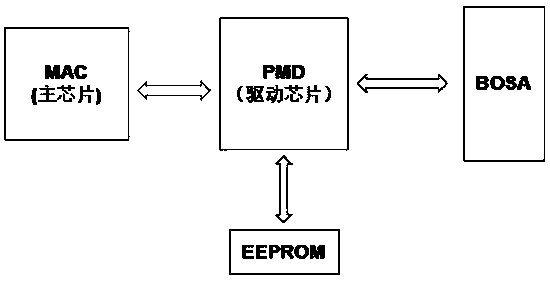
[0015] Such as figure 1 As shown, the working principle of ONU transmission is: an electrical signal of a certain code rate is sent from the main chip to the driver chip through a differential line in the form of a modulated signal. After the driver chip processes the received data signal, it will drive the semiconductor laser LD to emit a modulation signal of a corresponding rate. light signal.

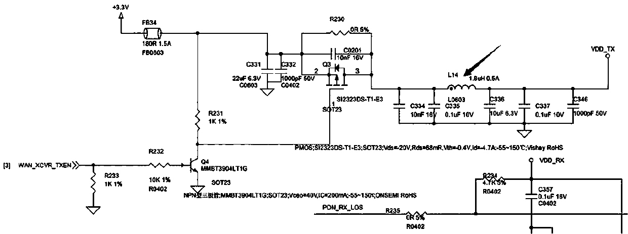
[0016] A method for verifying the quality of a 10G EPON asymmetric ONU emission eye diagram, comprising the following steps: S1: analyzing interference sources and interference methods; S2: analyzing potential interference generation links, including BOB drive circuit power system, BOSA device and main chip to drive The modulat...


PUM


Abstract

The invention discloses a 10G EPON asymmetric ONU emission optical eye pattern quality verification method. The method comprises the following steps: S1, analyzing an interference source and an interference mode; S2, analyzing a potential interference generation link, wherein the potential interference generation link comprises a BOB driving circuit power supply system, a BOSA device and a modulation signal from a main chip to a driving chip; and S3, setting experiments for each link in the step S2, and verifying the interference state. The problem is analyzed simplest, most directly and mosteffectively, and the direct reason of the interference problem is determined.

Description

technical field [0001] The invention relates to the field of 10G EPON, in particular to a method for verifying the quality of an eye diagram of a 10G EPON asymmetrical ONU emitting light. Background technique [0002] As the first and mature next-generation PON technology, 10G EPON technology conforms to the development trend of the network. It has the advantages of large bandwidth, large splitting ratio, compatible networking with EPON, unified network management, and smooth upgrade. 10GEPON and EPON come down in one continuous line. Use the existing network to directly increase the speed by 10 times, and perfectly match the bandwidth planning of domestic telecom operators, support the realization of the medium and long-term planning goals of domestic telecom operators, and support the continuity of operators in IDC business, government and enterprise customer business, and family customers expand. At present, there are two forms of 10G EPON: asymmetric 10Gbit / sEPON and s...

Claims


Application Information

Patent Timeline
IPC IPC(8): H04B10/079H04B10/556H04B10/69
Inventor 王旭东杨伟强
Owner SICHUAN TIANYI COMHEART TELECOM
Learn More