Electric vehicle coupling heat management system with high safety

A technology for electric vehicles and management systems, applied in electric vehicles, circuits, electrical components, etc., can solve the problems of low safety, easily damaged batteries, and inability to quickly and normally use the temperature, and achieve the effect of quickly adjusting the temperature

Active Publication Date: 2019-06-28
QUZHOU COLLEGE OF TECH
View PDF5 Cites 4 Cited by
  • Summary
  • Abstract
  • Description
  • Claims
  • Application Information

AI Technical Summary

Problems solved by technology

[0004] The purpose of the present invention is to provide a high-safety coupling thermal management system for electric vehicles to solve the problems in the above-mentioned background technology that the safety is low, the temperature cannot be used quickly and normally, and the battery is easily damaged

Method used


Image

  • Electric vehicle coupling heat management system with high safety
  • Electric vehicle coupling heat management system with high safety

Examples


Embodiment 1

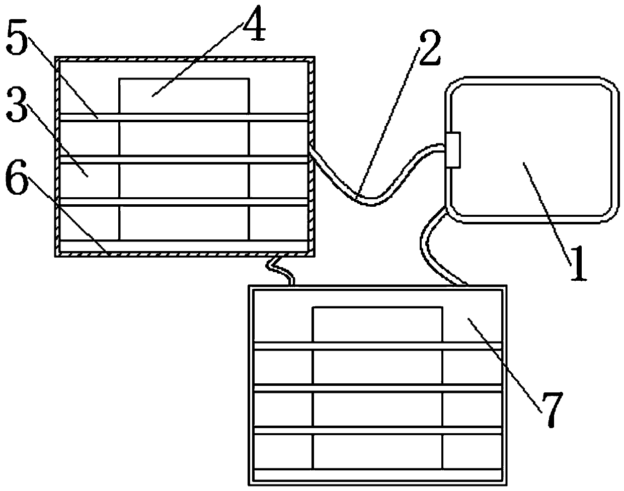
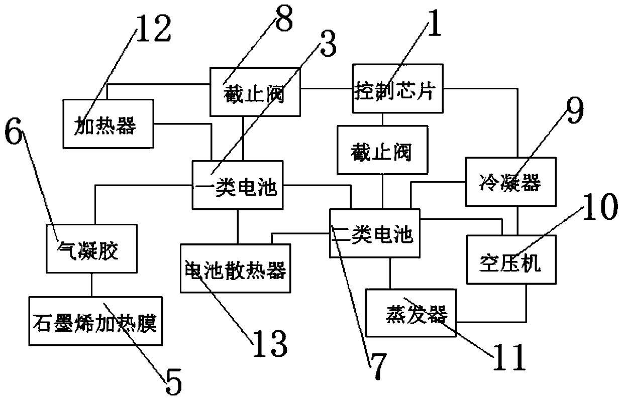
[0025] see figure 1 to attach figure 2 , a high-safety electric vehicle coupling thermal management system, mainly using control chip 1, wire 2, first-class battery 3, battery cell 4, second-class battery 7, stop valve 8, condenser 9, air compressor 10, The combination of evaporator 11, heater 12 and battery radiator 13 forms a high-safety electric vehicle coupling thermal management system;

[0026] The control chip 1 is electrically connected to the first-class battery 3, the second-class battery 7, the condenser 9, the air compressor 10, the evaporator 11, the heater 12, and the battery radiator 13 through electric wires 2, and the first-class battery 3 Airgel 6 is wrapped with screws on the outside, and cells 4 are installed inside the first-class battery 3 and second-class battery 3 .

Embodiment 2

[0028] A graphene heating film 5 is installed on one side of the internal cell 4 of the first-class battery 3, and a battery radiator 13 is installed on one side of the first-class battery 3 and the second-class battery 7, and a battery radiator 13 is installed on one side of the first-class battery 3. Heater 12, and the internal temperature of the first type battery 3 is 25-35°C, one side of the second type battery 7 is equipped with an evaporator 11, an air compressor 10 and a condenser 9 through the wire 2, and the internal temperature of the second type battery 7 is -10-2°C, and the first-class battery 3 and the second-class battery 7 are electrically connected through the wire 2, and the control chip 1 quickly controls the first-class battery 3, the condenser 9, the air compressor 10, and the evaporator through the cut-off valve 7 11. The heater 12 and the battery radiator 13, and the condenser 9 and the air compressor 10 are connected to the cockpit air-conditioning throu...

Embodiment 3

[0030] First, install this system. When the temperature of the electric vehicle is low, the control chip will open the first battery through the cut-off valve, the first battery will generate current, and the first battery will maintain the internal temperature of the first battery at 25-35°C through the heater. , then a type of battery drives the car through the electric drive system, and the graphene heating film wraps one side of the cell, which makes the heat transfer efficiency of the cell higher, and makes the heating effect of the type of battery relatively better, and makes the interior of the electric vehicle heat up quickly , when the temperature of the electric vehicle is high, the control chip will turn off the first battery and the heater through the cut-off valve, and turn on the second battery, and the second battery will keep the internal temperature at -10 through the condenser, air compressor and evaporator -2°C, which makes the interior of the electric vehicl...


PUM


Abstract

The invention discloses an electric vehicle coupling heat management system with high safety, which mainly uses the combination of a control chip, a wire, a class I battery, a battery cell, a class IIbattery, a globe valve, a condenser, an air compressor, an evaporator, a heater and a battery radiator to form the electric vehicle coupling heat management system with high safety. The control chipis connected with the class I battery, the class II battery, the condenser, the air compressor, the evaporator and the battery radiator respectively through the wire; when the internal temperature ofthe class I battery is higher than 35 DEG C, the control chip transmits the internal current of the class I battery to the inside of the class II battery, so that the heat management system can quickly transfer and adjust the energy, so as to avoid the damage of the battery when the internal temperature is higher and the life is lower; by setting an aerogel and graphene heating film, the thermal diffusion can be restrained by the aerogel and graphene heating film when the battery cell is out of control.

Description

technical field [0001] The invention relates to the technical field of electric vehicles, in particular to an electric vehicle coupled thermal management system with high safety. Background technique [0002] Electric vehicles use batteries as the power source. The power battery system is a complex system integrating battery technology, electronic control technology, structural design technology and thermal energy analysis technology. Coupling refers to the transmission of energy from a medium (such as a metal wire, optical fiber) to Another medium process, the thermal management system is mainly composed of heat-conducting medium, measurement and control unit, and temperature control equipment. Therefore, with the large-scale promotion of electric vehicles, the safety needs to be further improved. The existing pure electric vehicle thermal management system mainly The function is to regulate the temperature of the overall components of the pure electric vehicle to ensure th...

Claims


Application Information

Patent Timeline
Patent Type & Authority Applications(China)
IPC IPC(8): B60L58/26B60L58/27H01M10/613H01M10/615H01M10/625H01M10/6569H01M10/6571H01M10/635
CPCY02E60/10Y02T10/70
Inventor 巫少龙魏小华张新星罗方赞徐文俊
Owner QUZHOU COLLEGE OF TECH
Why Eureka
Try Eureka