

Method for predicting formation temperature of high temperature ferrite in Fe-Mn-Si-Cr-Ni alloy
A high-temperature ferrite and nickel alloy technology, applied in the field of shape memory alloys, can solve problems such as large prediction deviation, and achieve the effects of high accuracy, simple and fast method, and low cost
Inactive Publication Date: 2019-06-28
SICHUAN UNIV
View PDF7 Cites 0 Cited by
- Summary
- Abstract
- Description
- Claims
- Application Information
AI Technical Summary
Problems solved by technology
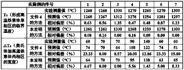
Document 4 (patent application number: 201810280668.4) discloses a method for predicting the temperature zone of the austenite plus high-temperature ferrite dual-phase zone of iron-manganese-silicon-based alloys, but the relative deviation between the predicted value of this method and the experimental measured value is 2% and the prediction deviation of the width of the two-phase region of austenite plus high-temperature ferrite is larger
Method used
View moreImage
Smart ImageViewing Examples

Examples
Embodiment 1
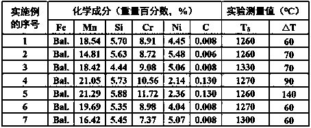
[0012] The weight percentage (%) of each element in the alloy: Mn 18.54, Si 5.70, Cr 8.91, Ni 4.45, C 0.008.
[0013] Calculate T according to the method of the present invention δ = 1261℃, the relative deviation is |(1261-1260)÷1260×100%|=0.08%; △T= 64℃, the relative deviation is |(64-60)÷60×100%|=6.67%.
[0014] T is calculated according to the method in Comparative Text 4 δ = 1268℃, the relative deviation is |(1268-1260)÷1260×100%|=0.63%; △T= 74℃, the relative deviation is |(74-60)÷60×100%|=23.33%.
Login to View More PUM
 Abstract
The invention discloses a method for predicting a formation temperature range of a high temperature ferrite in a Fe-Mn-Si-Cr-Ni alloy. The method is that a critical temperature Tsigma of forming a high temperature ferrite single-phase zone and a width delta T of an austenite plus high temperature ferrite two-phase zone can be calculated directly by putting the weight percentage of each element inthe alloy into a formula. The method is simple and easy to execute, has an accurate the prediction result, can be used as a tool to design the composition of the Fe-Mn-Si-Cr-Ni alloy with high recovery strain and no training and to formulate the heat treatment process, and has important engineering value.
Description
technical field [0001] The invention relates to the field of shape memory alloys, in particular to a method for predicting the formation temperature range of high-temperature ferrite in iron-manganese-silicon-chromium-nickel alloys. The method only needs to know the weight percentage of each element in the iron-manganese-silicon-chromium-nickel alloy, and can quickly obtain the formation temperature range of high-temperature ferrite in the alloy. The above method can be used as a tool for the composition design and heat treatment process of Fe-Mn-Si-Cr-Ni alloy with high recoverable strain without training. Background technique [0002] Iron-manganese-silicon-chromium-nickel shape memory alloy has the advantages of high strength, good plasticity, easy processing, weldability, corrosion resistance, and low price. It is a kind of shape memory alloy with great industrial application prospects. Document 1 (patent number: 201410102165.X) discloses a method for preparing a traini...
Claims
Login to View More Application Information
Patent Timeline
 IPC IPC(8): C21D6/00G06F17/50
Inventor彭华备雍立秋王改霞文玉华
OwnerSICHUAN UNIV