
A high-dynamic optical projection tomography method and device

A technology of optical projection tomography, imaging method, applied in image data processing, 2D image generation, instruments, etc., can solve the problems of reducing the degree of image distortion, low authenticity, low rank, etc.

Active Publication Date: 2019-06-28
FOSHAN UNIVERSITY
View PDF2 Cites 1 Cited by
  • Summary
  • Abstract
  • Description
  • Claims
  • Application Information

AI Technical Summary

Problems solved by technology

However, when the technology obtains less data, it is difficult to obtain a sufficiently low-rank matrix while maintaining the same difference on other singular value vectors.
The normalization algorithm area exposure time correction method uses the normalization algorithm to correct the exposure time of different areas. On the basis of overcoming the nonlinear response of the camera, the exposure time of each pixel on the output image is consistent, which reduces the image quality. The degree of distortion makes the imaging result more in line with the characteristics of human eye recognition; however, the lower part of the image fused by this method is slightly different from the higher part. The situation does not match, and the authenticity of the sample obtained when performing the OPT back-projection algorithm (Optical Projection Tomograthy, optical projection tomography) is low
[0004] All in all, the existing high-dynamic imaging methods of optical projection tomography three-dimensional imaging technology, such as the method of correcting the exposure time of different regions by using the normalization algorithm, have large errors in obtaining sample structure information

Method used


Image

  • A high-dynamic optical projection tomography method and device
  • A high-dynamic optical projection tomography method and device
  • A high-dynamic optical projection tomography method and device

Examples


Embodiment Construction

[0040] The concept, specific structure and technical effects of the present disclosure will be clearly and completely described below in conjunction with the embodiments and drawings, so as to fully understand the purpose, scheme and effect of the present disclosure. It should be noted that, in the case of no conflict, the embodiments in the present application and the features in the embodiments can be combined with each other.

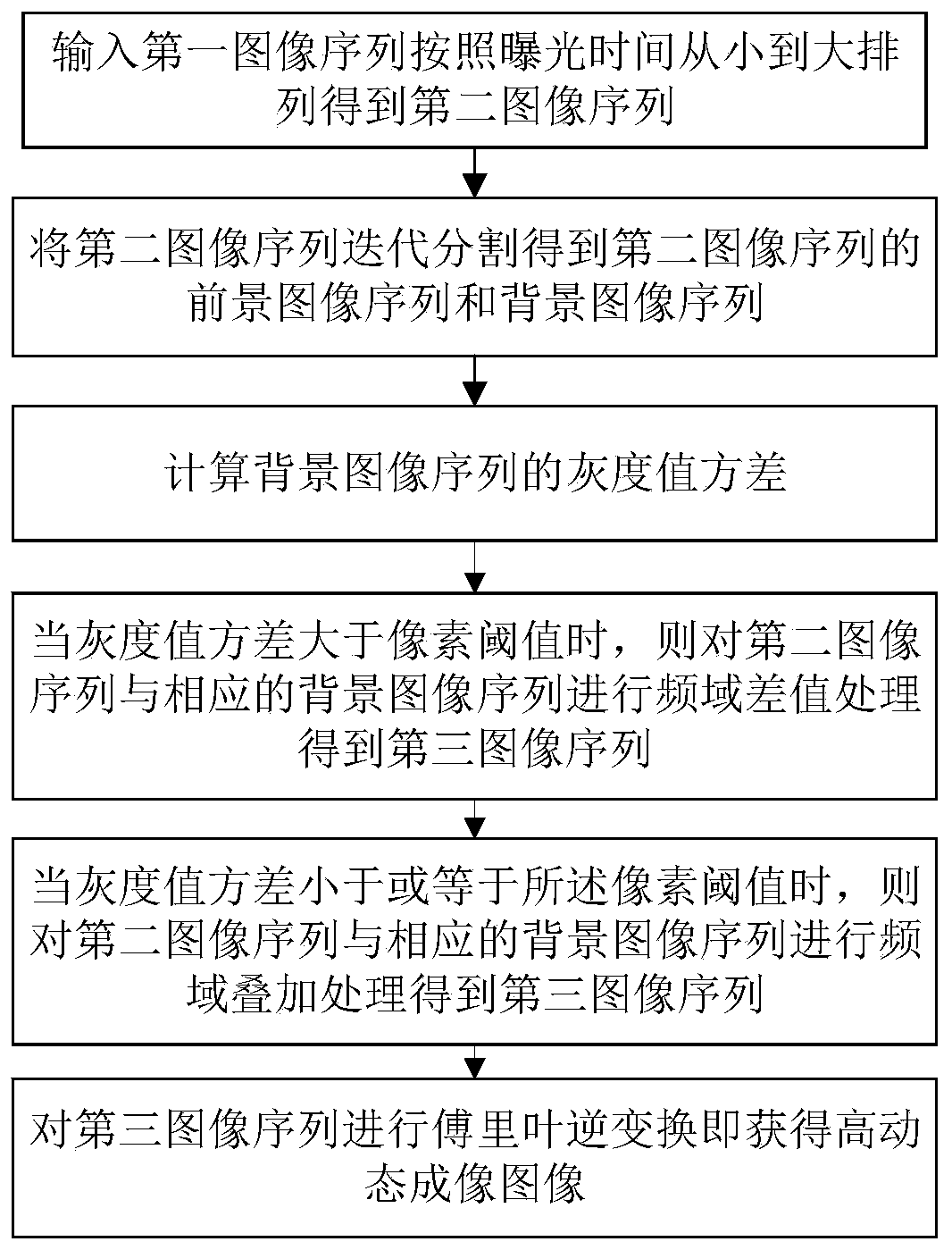
[0041] Such as figure 1 Shown is a flow chart of a high dynamic optical projection tomography method according to the present disclosure, combined below figure 1 A high dynamic optical projection tomography method according to an embodiment of the present disclosure will be described.

[0042] The present disclosure proposes a high dynamic optical projection tomography method, which specifically includes the following steps:

[0043] Step 1, input the first image sequence and arrange according to the exposure time from small to large to obtain the ...


PUM


Abstract

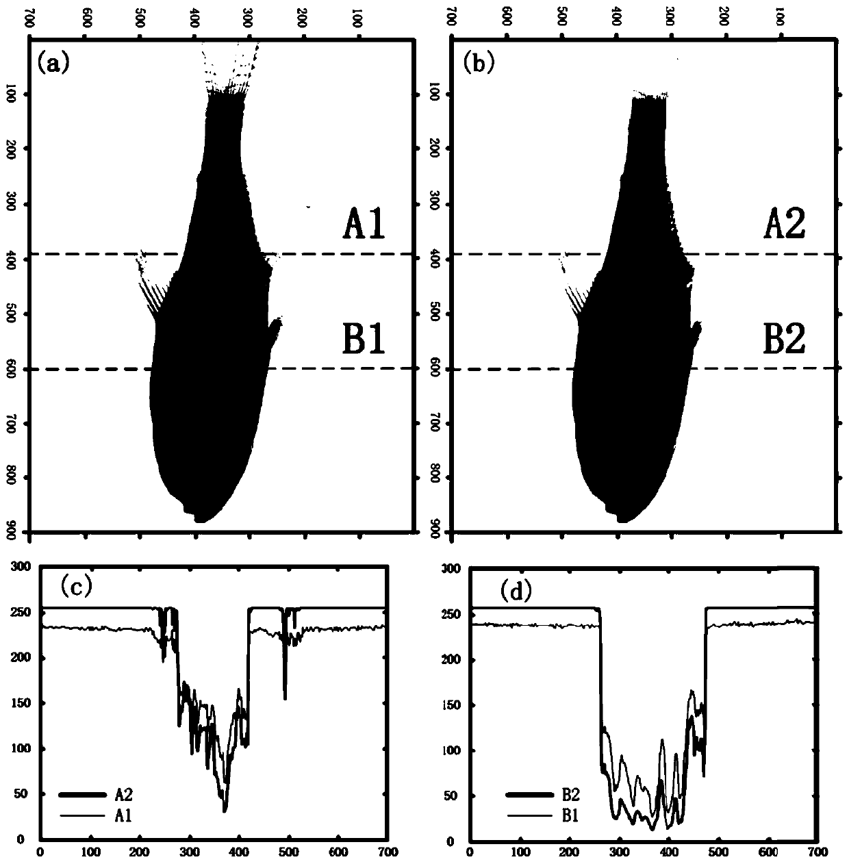
The invention discloses a high-dynamic optical projection tomography method and device. images at different exposure times and background images at corresponding exposure times are processed and fusedin a frequency domain; a complete and real image with high contrast degree details is obtained; filtering back projection is performed to obtain three-dimensional image reconstruction; The inventionprovides a method for superposing threshold difference values on a two-dimensional Fourier plane. a three-dimensional imaging result is obtained through comparison; compared with a traditional OPT three-dimensional imaging result, more abundant information of the sample is obtained; the distribution information of the surface layer and the internal structure of the sample can be completely stored;and moreover, high contrast detail information which cannot be obtained under a single exposure condition is obtained, a more real image is obtained compared with a method for correcting the exposuretime of different areas by adopting a normalization algorithm, and fine three-dimensional structure imaging of a sample with a complex space structure is realized.

Description

technical field [0001] The present invention relates to the technical fields of image processing, three-dimensional imaging and high dynamic imaging, and more specifically relates to a high dynamic optical projection tomography method and device. Background technique [0002] Optical projection tomography is a new type of three-dimensional (3-D) imaging technology for small biological specimens. This 3D imaging technique uses optical scavenger cleans or takes transparent samples, and uses ultraviolet, visible and near-infrared spectra to transmit photons through the sample to calculate the three-dimensional structure. In order to overcome the problem that the range of the camera response curve is too short and the transparency of different regions of the sample varies greatly, there are many high-dynamic imaging methods, such as: using HDR sensor (High-Dynamic Range, high-dynamic range sensor) hardware acquisition; linear image solution low-rank Matrix high dynamic fusion; ...

Claims


Application Information

Patent Timeline
Patent Type & Authority Applications(China)
IPC IPC(8): G06T11/00
Inventor 韩定安李秉尧林秋萍张艳婷王雪花王茗祎曾亚光谭海曙
Owner FOSHAN UNIVERSITY
Learn More