Thermoelectric device with firm structure

A thermoelectric device and solid technology, applied in the direction of electrical components, generators/motors, etc., can solve the problems of large thermal shock of thermoelectric devices, low thermoelectric conversion efficiency, and shortened life of thermoelectric devices, so as to slow down the flow speed and improve thermal efficiency. The effect of improving transmission efficiency and stability

Active Publication Date: 2019-06-28
朱梁锋
View PDF7 Cites 1 Cited by
  • Summary
  • Abstract
  • Description
  • Claims
  • Application Information

AI Technical Summary

Problems solved by technology

However, in some fields, the utilization rate is not high. In the prior art, in order to increase the heat transfer rate, materials with good thermal conductivity such as metal are generally directly selected, and the heat source is directly contacted with the thermoelectric device. However, metal is used to directly conduct Heat transfer, the thermal impact on the thermoelectric device is large, it may exceed the thermal capacity of the thermoelectric device in an instant, and the impact of multiple temperature changes will reduce the life of the thermoelectric device, causing waste, and the thermoelectric conversion efficiency is not high
In addition, in some fields, such as water heaters, when heated, the pressure in the insulation chamber will increase, and the temperature will increase, causing thermoelectric devices to expand with heat and contract with cold, and the thermal stress of the devices caused by thermoelectric devices under high thermal shock Increase, even cause cracks, damage the device, and affect the life of the device

Method used


Image

  • Thermoelectric device with firm structure
  • Thermoelectric device with firm structure
  • Thermoelectric device with firm structure

Examples


Embodiment 1

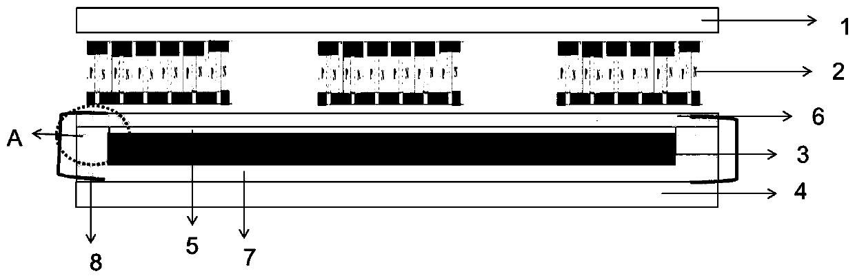
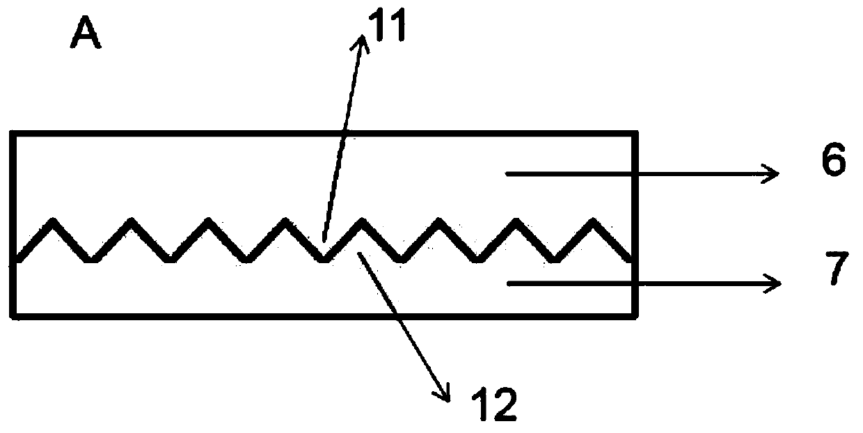
[0019] Such as figure 1 As shown, the present invention provides a thermoelectric device with firm structure, including a thermoelectric device 2 and a heat transfer component, a heat transfer component is arranged between a heat source 4 and a thermoelectric device 2, and the heat transfer component includes a cavity, an upper part of the cavity 6 and the cavity lower part 7, the cavity upper part 6 is detachably connected to the cavity lower part 7, and the connection between the cavity upper part 6 and the cavity lower part 7 is a toothed connection, such as figure 2 shown, for figure 1 Schematic diagram of the structure at the connection part A of the middle cavity, the bottom surface of the connection part 6 of the upper part of the cavity is provided with a toothed part 11, and the top surface of the connection part 7 of the lower part of the cavity is provided with a bottom surface of the connection part of the upper part of the cavity The tooth-shaped part one 11 is ...

Embodiment 2

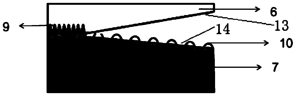
[0022] Such as image 3 As shown, the structure of the thermoelectric device in the second embodiment is similar to that in the first embodiment, the main difference is that the connection part of the heat transfer component in the second embodiment is different, and the upper part of the cavity of the heat transfer part in the second embodiment is close to the connecting part There is an inclined part 13, and the phase change material that is convenient for cooling is left from the upper part; the connecting part 9 near the edge of the lower part of the cavity is provided with an inclined part 2 14, and a plurality of protrusions 10 are arranged at intervals on the surface of the inclined part 2 14. The surface of the plurality of protrusions 10 is arc-shaped, which can slow down the flow velocity of the phase change material to a certain extent, so that the phase change material flowing to this part slowly absorbs heat, so as to reduce the phase change material flowing down f...


PUM


Abstract

The invention relates to a thermoelectric device with a firm structure. The device comprises a thermoelectric device and a heat transfer part. A heat transfer member is provided between a heat sourceand the thermoelectric device. The upper and lower parts of a cavity are detachably connected through a connecting part, wherein the connection is tooth-shaped connection. A tooth-shaped part I is arranged on the bottom surface of the connecting part of the upper part of the cavity, and a tooth-shaped part II matched with the tooth-shaped part I on the bottom surface of the connecting part of theupper part of the cavity is arranged on the top surface of the connecting part of the lower part of the cavity. A phase change material is arranged in the cavity, and a plurality of bulges are arranged at the bottom close to the edge part, thereby alleviating the flowing speed of the phase-change material to a certain extent, and enabling the phase-change material flowing to the position to absorbheat slowly, so as to reduce the temperature difference between the phase-change material flowing down from the edge and the phase-change material in the center of the bottom, prevent the sputteringcaused by too large temperature difference of the phase-change material from affecting the heat transfer efficiency and damage to a heat transfer component, and prevent the phase-change material fromflowing to the edge.

Description

technical field [0001] The invention relates to a power generating device, in particular to a thermoelectric device with firm structure. Background technique [0002] With the continuous depletion of traditional energy sources such as oil and coal, which seriously restricts economic development, and the pollution of traditional energy sources is large, and produces a large amount of waste heat, waste residue, waste water, waste gas, etc., which has a serious impact on the environment and endangers the ecological environment of the earth. Nowadays, people Continuously develop new energy sources in order to replace traditional energy sources and avoid environmental impacts. New energy technologies such as solar energy and lithium batteries continue to develop and mature, and have become the main research fields of new energy sources. However, the existing technologies, including traditional energy sources and the above-mentioned new energy technologies, all have certain energy...

Claims


Application Information

Patent Timeline
Patent Type & Authority Applications(China)
IPC IPC(8): H02N11/00
Inventor 朱梁锋汪育仁
Owner 朱梁锋
Why Eureka
Try Eureka