Gas pipeline pavement method and support structure thereof
A technology for gas pipelines and laying methods, which is applied in pipeline support, pipeline laying and maintenance, mechanical equipment, etc., can solve the problems of expensive investment, difficult construction, high construction cost, etc., and achieve stable and reliable connection, low construction difficulty, The effect of reducing engineering construction cost
- Summary
- Abstract
- Description
- Claims
- Application Information
AI Technical Summary
Problems solved by technology
Method used
Image

Examples
Embodiment 1
[0050] A kind of gas pipeline laying method of the present invention, its schematic flow chart is as Figure 1 to Figure 10 As shown, it mainly includes the following steps:
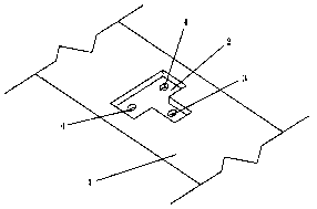
[0051] The first step is to open a plurality of "T"-shaped grooves 2 along the bridge direction on the sidewalk 1 of the bridge, and drill three through holes along the bridge from top to bottom in each groove 2. The three through holes Arranged in the shape of "pin" along the direction of the bridge, one of which is the hanger hole 3, and the other two are load-bearing holes 4, the distance between the connection line of the two load-bearing holes 4 and the hanger hole 3 is 650mm, two Load-bearing holes 4 are arranged along the direction of the bridge, and then the gas pipeline (epoxy anti-corrosion steel pipe) to be laid is placed on the sidewalk 1, and the gas pipeline is cut into multiple pipeline sections 5.
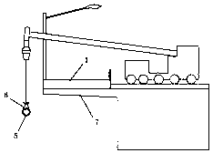
[0052] The second step is to bind the cable 6 in the middle of the pipeline section 5, ho...
Embodiment 2
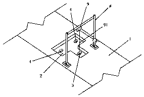
[0062] Such as Figure 10 to Figure 13 As shown, a support structure for laying gas pipelines on the underside of a bridge of the present invention includes a bracket 13, a buckle 14, a boom 15, an auxiliary fixing plate 16, an auxiliary fixing bolt 17 and an oblique connecting plate 18. Wherein, the buckle 14 is installed on the bracket 13 , and two ends of the bracket 13 are respectively provided with a hoisting through hole (not shown in the figure) on both sides of the buckle 14 . Suspender rod 15 is two, and two suspension rods 15 are respectively pierced in two hoisting through holes, and the upper and lower ends of suspension rod 15 are all provided with nuts, and the lower end of suspension rod 15 is fastened and connected with bracket 13 by nut. The middle part of the auxiliary fixing plate 16 has a positioning through hole, and the auxiliary fixing bolt 17 is penetrated in the positioning through hole. The upper and lower ends of the auxiliary fixing bolt 17 are prov...
PUM
 Abstract
Description
Claims
Application Information
 - R&D Engineer
- R&D Manager
- IP Professional
- Industry Leading Data Capabilities
- Powerful AI technology
- Patent DNA Extraction
Browse by: Latest US Patents, China's latest patents, Technical Efficacy Thesaurus, Application Domain, Technology Topic.
© 2024 PatSnap. All rights reserved.Legal|Privacy policy|Modern Slavery Act Transparency Statement|Sitemap